










Product Details
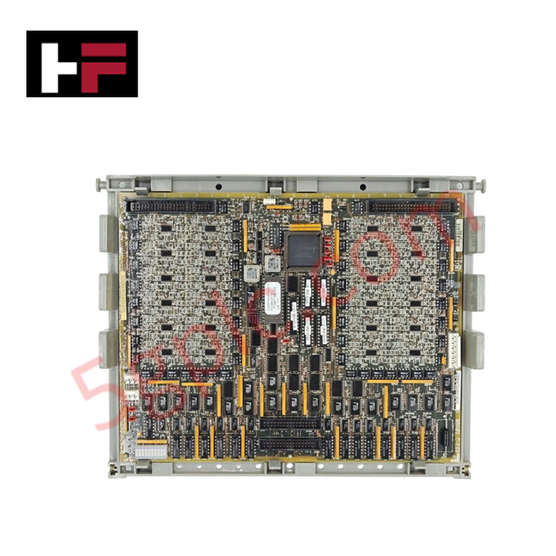
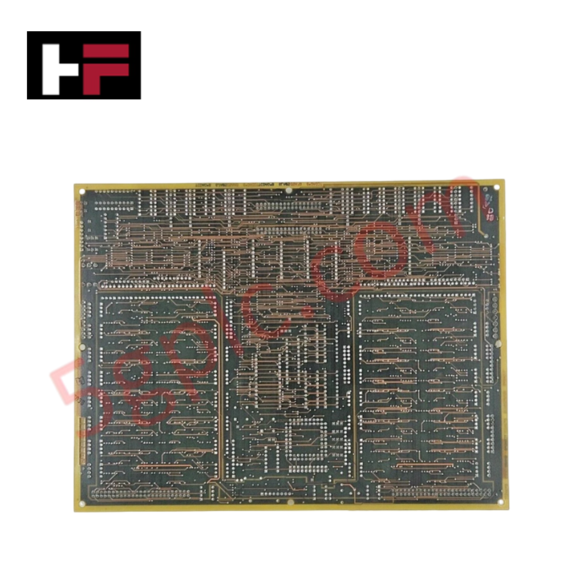
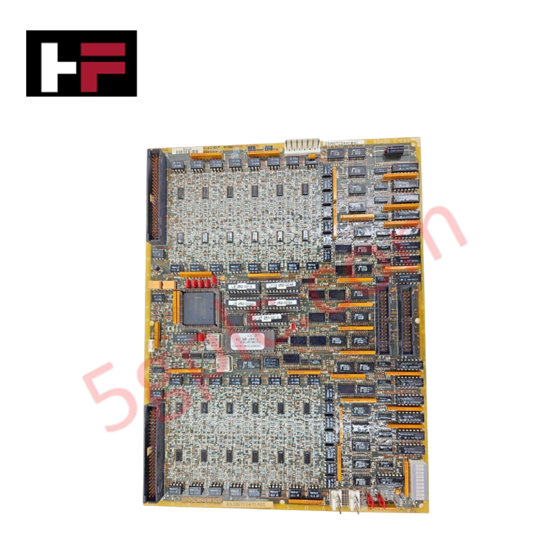
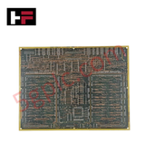
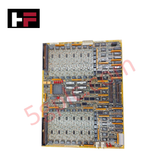
Configured for digital signal processing and I/O interface management in Mark V drive systems, the GE DS200TCDAH1B (DS200TCDA Digital I/O Board) provides direct physical execution of logic state monitoring and command relaying.
Hardware Specifications
| Parameter | Specification |
|---|---|
| Model | DS200TCDAH1B |
| Brand | GE |
| Core Performance | 1 microprocessor, multiple PROM modules, 2 50-pin I/O connectors |
Industrial Control & Firmware Compatibility
The DS200TCDAH1B functions as a localized processing node within the Mark V control architecture, managing digital input and output state synchronization. The board utilizes an onboard microprocessor and PROM modules to execute control logic, with backplane bus communication velocity optimized for real-time turbine drive management. Firmware flash compatibility is strictly dependent on the revision level; the B-series iteration requires specific system-level matching to ensure I/O density scaling is correctly interpreted by the host processor. Integration with external terminal boards (DS200DTBA and DS200DTBB) is facilitated via JQ and JR 50-pin connectors, which serve as the primary conduits for deterministic signal transmission.
Frequently Asked Questions
Q: Can the onboard PROM modules be updated in the field?
A: No. The PROM modules are pre-programmed; field modifications to the control logic stored on these modules are not supported. If logic changes are required, a replacement board with the correct revision level must be utilized.
Q: How are test points utilized for board-level diagnostics?
A: Test points labeled TP1 through TPx allow a technician to probe individual circuit voltages using a calibrated testing device. These points should only be accessed while the board is powered in a diagnostic state to isolate localized component faults.
Field Installation Guidelines
- Ribbon Cable Interface: When connecting the JQ and JR 50-pin headers to the DS200DTBA or DS200DTBB boards, ensure ribbon cables are properly keyed and seated. Incorrect orientation will cause signal misalignment and loss of I/O communication.
- Jumper Settings: Verify that all eight jumpers (JP1 through JP8) are positioned according to the specific drive configuration documentation. Do not alter jumper positions unless directed by technical specifications, as this defines the board's operational logic.
- Signal Grounding: Ensure the board chassis is securely mounted to the drive cabinet to maintain a solid reference ground. Proper grounding is necessary to minimize electromagnetic interference on the 50-pin digital signal paths.
- Microprocessor Handling: Avoid contact with the microprocessor and PROM pins. Use an anti-static wrist strap during all phases of installation to prevent permanent damage from electrostatic discharge.
Additional Information
- 100% Genuine Parts: All products are original and authentic, ensuring reliable industrial performance.
- 30-Day Refund Guarantee: Return any in-stock item within 30 days in original, unopened packaging for a full refund (excluding shipping and fees).
- 12-Month Warranty: Covers defects in materials or workmanship; excludes misuse, normal wear, or unauthorized modifications.
- Worldwide Shipping: We ship via USPS, UPS, FedEx, and DHL. Delivery times vary by country and may be subject to customs or import fees.
- Support & Contact: Technical and warranty assistance is available anytime. Contact us here: Contact.
- Purchase Guidance: Check product specifications and compatibility carefully before ordering to ensure proper application.


Tech & Buying Guide

The Shift to Flexible IO Modules in Modern Industrial Automation
Traditional control systems rely on dedicated Input Output (IO) cards for industrial automation. Each conventional module processes a single signal type, such as Digital Input (DI), Digital Output (DO), Analog Input (AI), or Analog Output (AO). A standard 16-channel card accepts only one specific channel type across all ports. This inflexible hardware design often creates severe engineering bottlenecks during project execution. Engineers frequently must install entirely new cards to accommodate a single extra sensor. Consequently, late design changes increase control cabinet space requirements and drive up project costs.

DCS Commissioning Steps in Industrial Automation Projects
Commissioning a Distributed Control System (DCS) represents a crucial milestone when deploying modern process automation infrastructure. Field engineers must execute systematic verification steps to transition complex control hardware from static installation to dynamic plant control. Proper commissioning ensures that controllers, I/O modules, network switches, and HMI software operate in strict compliance with engineering design specifications before introducing live process fluids.

PLC and DCS Control System Spares Strategy: Engineering Guidelines
Modern factory automation relies on high-speed fiber optic backbones to link distributed control systems across noise-intensive industrial environments. Unlike copper wiring, optical fibers transmit data via light pulses, making them completely immune to electromagnetic interference (EMI). Field engineers must master optical cable joining and fusion splicing techniques to guarantee low-loss data transmission across critical Programmable Logic Controller (PLC) and Distributed Control System (DCS) nodes.