


Product Details
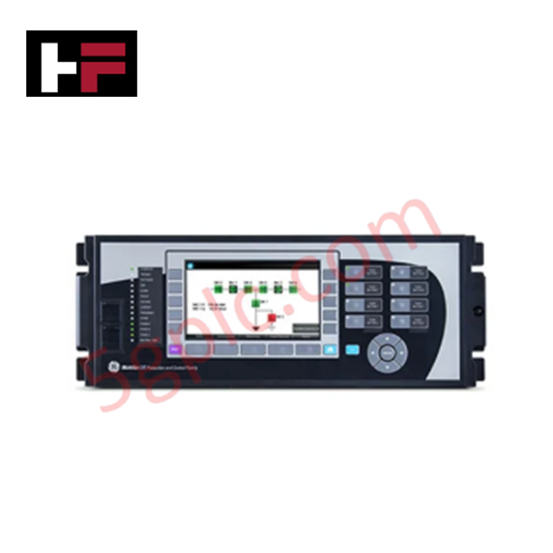
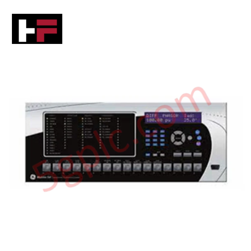
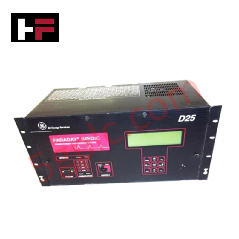
Configured for generator monitoring and grid-side fault isolation, the GE G60-GO1-HCH-F8F-H67-M8F-P6D-U6D-W6C (G60 Generator Protection System) provides direct physical/electrical execution of overcurrent protection, synchronization, and fault-based trip sequences.
Hardware Specifications
| Parameter | Specification |
|---|---|
| Model | G60-GO1-HCH-F8F-H67-M8F-P6D-U6D-W6C |
| Brand | GE |
| Operating Temp | Standard industrial ambient |
| Protection | Overcurrent, short circuit, ground fault |
| Control | Generator synchronization and trip |
Profinet / EtherNet/IP Deterministic Networks and I/O Density Scaling
The G60 processing engine utilizes high-speed logic to evaluate generator health and isolate fault conditions within deterministic time windows. Backplane bus communication velocity must be calibrated to align with the facility's supervisory control requirements. Firmware flash compatibility is strictly controlled; users must ensure that logic updates are validated against the specific revision of the I/O processing board to maintain deterministic performance during communication with plant-level SCADA systems. The architecture supports internal I/O density scaling to manage complex synchronization matrices and generator protection logic concurrently.
Frequently Asked Questions
Q: Can the G60 modules be hot-swapped during active generator operation?
A: No. Hot-swapping of protection modules is prohibited. The unit must be fully isolated from auxiliary power and primary sensing inputs to prevent inadvertent tripping or hardware damage to the backplane communication bus.
Q: How is the integrity of the protection logic verified during commissioning?
A: Verification should be performed via secondary injection testing of current and voltage signals. Protection thresholds and trip logic must be confirmed against the predefined generator safety parameters before the generator is synchronized to the utility grid.
Field Installation Guidelines
- Chassis Mounting: Secure the relay into the panel using the provided hardware. Ensure the installation adheres to required seismic and vibration standards to maintain enclosure integrity.
- Grounding: Establish a low-impedance connection between the chassis ground terminal and the station common earth-ground bus. This prevents electromagnetic interference from affecting low-level analog signal acquisition.
- Wiring Protocols: Separate protection sensing inputs (current and voltage transformers) from communication and control wiring within the cabinet. Utilize shielded cabling for all serial or Ethernet interfaces to minimize noise injection.
- Terminal Verification: Ensure all terminal blocks are fully seated and secured. Verify that phase rotation for current and voltage inputs matches the configuration settings of the internal synchronization logic.
Additional Information
- 100% Genuine Parts: All products are original and authentic, ensuring reliable industrial performance.
- 30-Day Refund Guarantee: Return any in-stock item within 30 days in original, unopened packaging for a full refund (excluding shipping and fees).
- 12-Month Warranty: Covers defects in materials or workmanship; excludes misuse, normal wear, or unauthorized modifications.
- Worldwide Shipping: We ship via USPS, UPS, FedEx, and DHL. Delivery times vary by country and may be subject to customs or import fees.
- Support & Contact: Technical and warranty assistance is available anytime. Contact us here: Contact.
- Purchase Guidance: Check product specifications and compatibility carefully before ordering to ensure proper application.


Tech & Buying Guide

Essential SCADA Features for Modern IoT-Enabled Industrial Automation
The convergence of traditional SCADA systems with the Industrial Internet of Things (IIoT) has redefined factory automation. Choosing a robust platform requires more than just standard monitoring capabilities. In this era of Industry 4.0, your supervisory system must bridge the gap between legacy control systems and enterprise-level data integration.

Selecting Rockwell Automation Allen-Bradley PLCs for Small and Mid-Sized Applications
Rockwell Automation remains a cornerstone in global industrial automation. Their Allen-Bradley brand provides a comprehensive portfolio of control systems designed to meet diverse production requirements. Choosing the right programmable logic controller (PLC) is critical for system reliability and scalability. This guide analyzes the Micro and Compact Logix families to help you select the optimal solution for small and medium-scale projects.

Strategic Selection: Choosing the Right SCADA Software for Your PLC Project
In industrial automation, the SCADA (Supervisory Control and Data Acquisition) system acts as the bridge between raw machine data and actionable human intelligence. Selecting the incorrect software platform can lead to integration bottlenecks, scalability issues, and excessive long-term maintenance costs. As an automation consultant with 15 years of experience, I have guided many projects through the selection process. Below are the essential criteria for choosing a platform that ensures both performance and longevity.