


Product Details
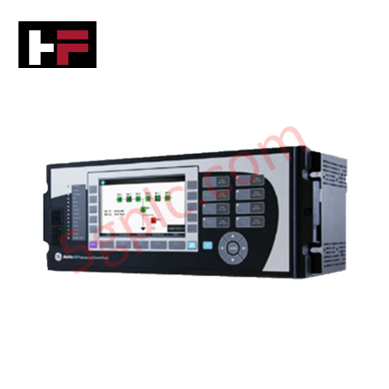
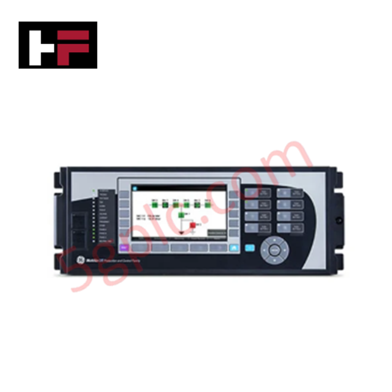
The GE G60E00HCH serves as the primary G60 Generator Protection System utilized to execute high-speed fault detection and automated protection control across industrial power generation platforms. The hardware processes physical analog and digital signals directly to protect multi-type turbine-driven and hydro-generating blocks. Operating via integrated communication buses, the device manages complex protective processing algorithms while updating an internal full-color graphical display to capture fault transients and continuous line measurements.
Hardware Specifications
| Parameter | Specification |
|---|---|
| Model | G60E00HCH |
| Brand | GE Multilin |
| Origin | Technical specifications determine factory origin |
| Weight | Unit specific / Internal card configuration dependent |
| Dimensions | Standard G60 panel mount footprint |
| Operating Temp | -40 to +70 deg C |
| Power Consumption | Base unit power consumption plus slot load variants |
| Protection Type | Generator protection relay |
| Communication Protocols | IEC 61850, Modbus, DNP3 |
| Interface Type | Integrated full-color graphical interface |
| Compliance Rating | IEEE C37.102 compliance standards |
| I/O Configuration | High-capacity digital and analog inputs/outputs |
Profinet and EtherNet/IP Deterministic Networks Integration
The processing unit relies on a deterministic internal bus architecture to process real-time generator metrics without runtime bottlenecks. By structuring discrete hardware priorities for incoming signal lines, the system maintains strict firmware flash compatibility across safety-interlocking states. This layout prevents communication overhead from industrial protocols like IEC 61850 or Modbus from delaying the sub-cycle execution loops required by primary generator fault-detection elements.
Frequently Asked Questions
Q: Does the G60E00HCH housing support live hot-swapping of internal I/O modules?
A: No. Internal modules and hardware expansion cards are not built for live hot-swap insertion. The main control power must be completely disconnected and isolated before servicing or replacing internal sub-assembly cards to prevent damage to backplane routing paths.
Q: How is the physical execution of high-speed protection outputs handled during processor logic updates?
A: Protective trip elements are processed by high-priority execution loops separate from front-panel display logic. While downloading configuration files, protective relay outputs transition to a pre-configured safe operational state to eliminate spurious tripping.
Field Installation Guidelines
- Chassis Grounding: Secure a dedicated, low-impedance copper earthing line from the frame grounding terminal on the rear chassis directly to the master station panel ground bus.
- Signal Cable Shielding: Ensure all low-voltage analog inputs and communication lines utilize shielded twisted-pair cables. Ground the outer copper shields at the cabinet entry gland panel only.
- Cable Pathway Separation: Separate all AC current transformer (CT) input leads and DC control power wiring from low-voltage digital signal and network communication buses by routing them through isolated metal conduits.
Additional Information
- 100% Genuine Parts: All products are original and authentic, ensuring reliable industrial performance.
- 30-Day Refund Guarantee: Return any in-stock item within 30 days in original, unopened packaging for a full refund (excluding shipping and fees).
- 12-Month Warranty: Covers defects in materials or workmanship; excludes misuse, normal wear, or unauthorized modifications.
- Worldwide Shipping: We ship via USPS, UPS, FedEx, and DHL. Delivery times vary by country and may be subject to customs or import fees.
- Support & Contact: Technical and warranty assistance is available anytime. Contact us here: Contact.
- Purchase Guidance: Check product specifications and compatibility carefully before ordering to ensure proper application.


Tech & Buying Guide

Essential SCADA Features for Modern IoT-Enabled Industrial Automation
The convergence of traditional SCADA systems with the Industrial Internet of Things (IIoT) has redefined factory automation. Choosing a robust platform requires more than just standard monitoring capabilities. In this era of Industry 4.0, your supervisory system must bridge the gap between legacy control systems and enterprise-level data integration.

Selecting Rockwell Automation Allen-Bradley PLCs for Small and Mid-Sized Applications
Rockwell Automation remains a cornerstone in global industrial automation. Their Allen-Bradley brand provides a comprehensive portfolio of control systems designed to meet diverse production requirements. Choosing the right programmable logic controller (PLC) is critical for system reliability and scalability. This guide analyzes the Micro and Compact Logix families to help you select the optimal solution for small and medium-scale projects.

Strategic Selection: Choosing the Right SCADA Software for Your PLC Project
In industrial automation, the SCADA (Supervisory Control and Data Acquisition) system acts as the bridge between raw machine data and actionable human intelligence. Selecting the incorrect software platform can lead to integration bottlenecks, scalability issues, and excessive long-term maintenance costs. As an automation consultant with 15 years of experience, I have guided many projects through the selection process. Below are the essential criteria for choosing a platform that ensures both performance and longevity.