


Product Details
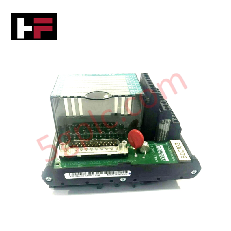
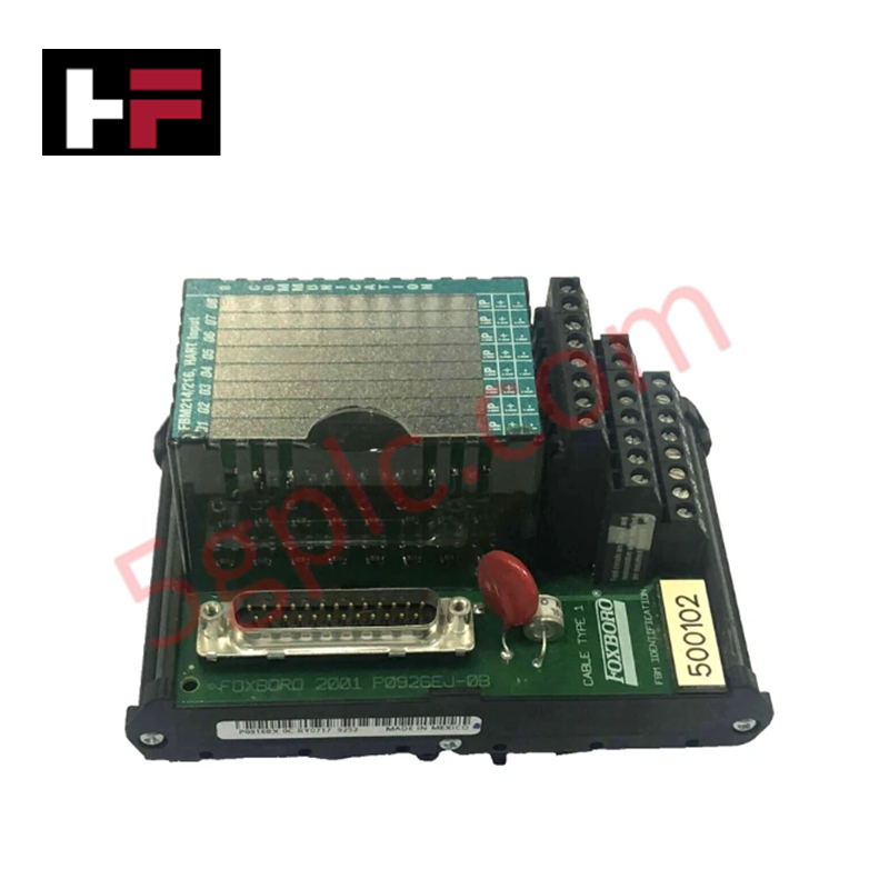
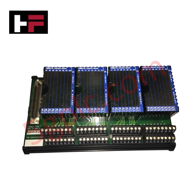
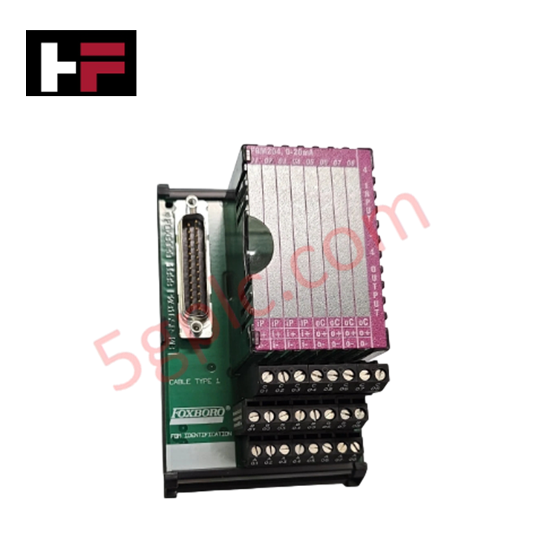
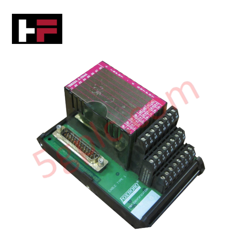
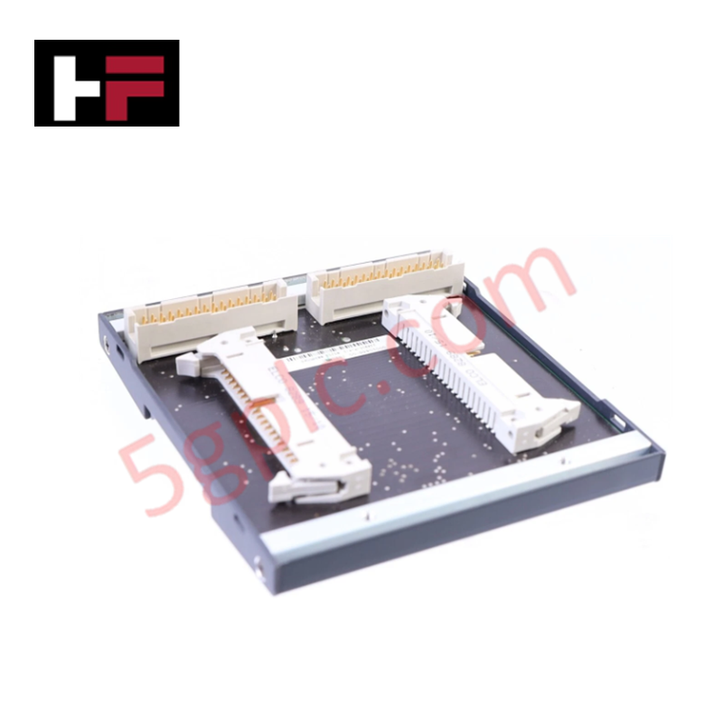
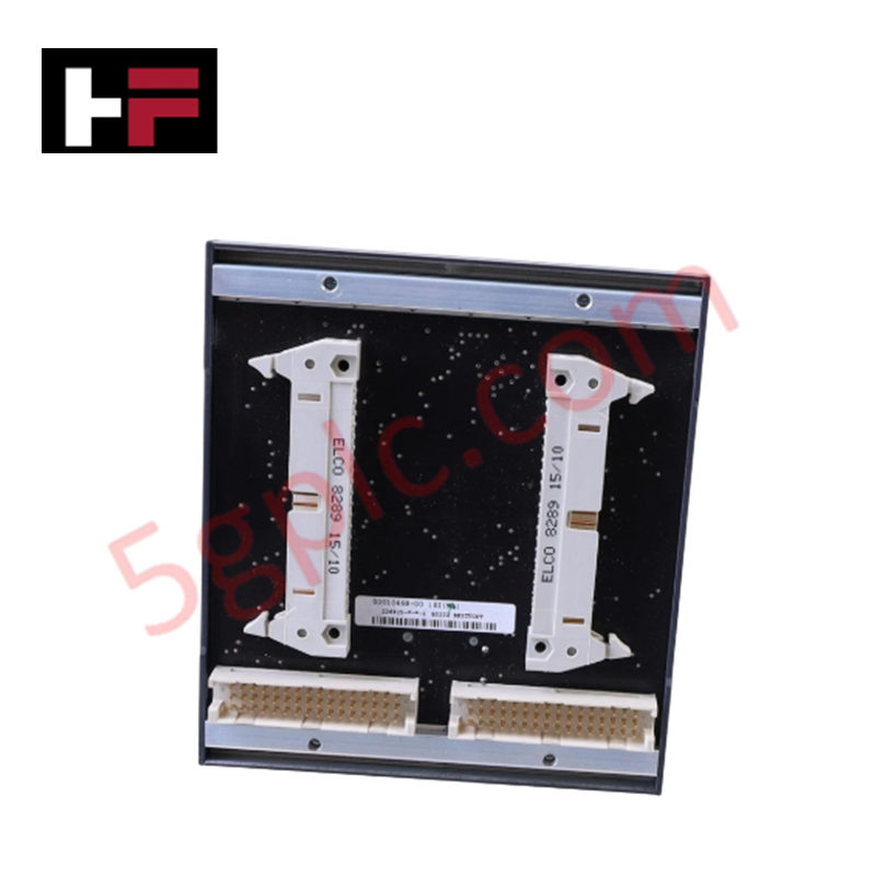
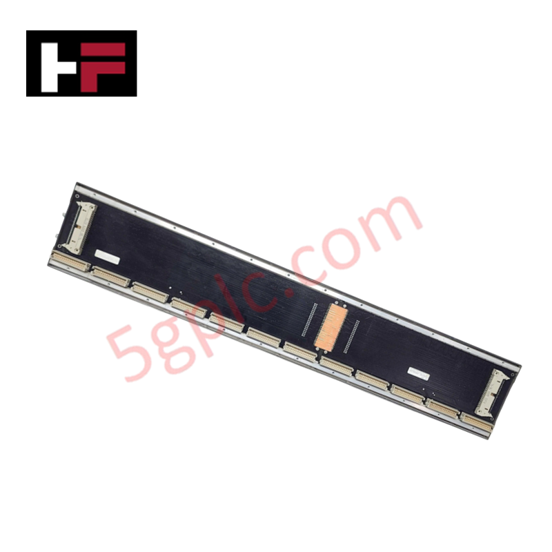
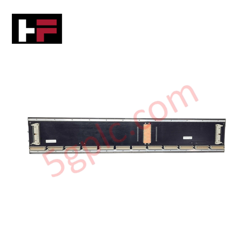
Configured for signal termination and interface distribution in Foxboro I/A Series control networks, the Foxboro Invensys P0916BX (P0916BX Terminal Assembly) provides direct physical/electrical execution. This component serves as the mechanical termination point for FBM214 and FBM216 field bus modules, facilitating the transition between field wiring and internal I/O circuitry via standardized compression terminals.
Hardware Specifications
| Parameter | Specification |
|---|---|
| Model | P0916BX |
| Brand | Foxboro Invensys |
| Origin | United States |
| Weight | 3.00 lbs |
| Dimensions | Standard DIN-rail mount form factor |
| Operating Temp | -20 deg C to 70 deg C |
| Power Consumption | Passive (no active electronic power draw) |
| Compatible Modules | FBM214, FBM216 |
| Terminal Type | Compression Screw / Spring Clamp |
DCS Process Instrumentation Connectivity
The P0916BX ensures signal integrity within the DCS infrastructure through optimized termination geometry. The assembly supports 4-20 mA HART loop protocol connectivity by providing dedicated test points and low-impedance paths for field instrumentation. The design incorporates channel-to-channel isolation physical barriers to minimize noise ingress and crosstalk during high-density signal integration. Field wires must be routed to prevent mechanical stress on the compression terminals, ensuring long-term connection stability in high-vibration control room environments.
Frequently Asked Questions
Q: Does the P0916BX terminal assembly support hot-swap operations for the connected FBM214/216 modules?
A: Yes, the mechanical design of the P0916BX allows for the removal and replacement of the associated FBM modules without requiring the disconnection of field wiring from the terminal assembly, provided the system bus power is managed according to site safety protocols.
Q: Are there specific torque requirements for the compression terminals?
A: Yes, ensure all field wires are secured within the compression terminals to a torque specification of 0.5 Nm to 0.7 Nm to maintain electrical contact and prevent thermal cycling failures.
Field Installation Guidelines
- Ensure the DIN-rail is securely mounted to the cabinet backplane and electrically bonded to the common ground bus.
- Align the P0916BX assembly with the rail and apply downward pressure until the latch mechanism engages.
- Strip field wires to the specified length (typically 8 mm to 10 mm) to ensure full contact within the compression housing without exposing excess copper.
- Verify that the shield drain wires are terminated at the designated grounding bar to minimize electromagnetic interference (EMI).
- Confirm the alignment of the FBM214/216 backplane connector before applying pressure to seat the module onto the P0916BX assembly.
Additional Information
- 100% Genuine Parts: All products are original and authentic, ensuring reliable industrial performance.
- 30-Day Refund Guarantee: Return any in-stock item within 30 days in original, unopened packaging for a full refund (excluding shipping and fees).
- 12-Month Warranty: Covers defects in materials or workmanship; excludes misuse, normal wear, or unauthorized modifications.
- Worldwide Shipping: We ship via USPS, UPS, FedEx, and DHL. Delivery times vary by country and may be subject to customs or import fees.
- Support & Contact: Technical and warranty assistance is available anytime. Contact us here: Contact.
- Purchase Guidance: Check product specifications and compatibility carefully before ordering to ensure proper application.


Tech & Buying Guide

Strategic Selection: Choosing the Right SCADA Software for Your PLC Project
In industrial automation, the SCADA (Supervisory Control and Data Acquisition) system acts as the bridge between raw machine data and actionable human intelligence. Selecting the incorrect software platform can lead to integration bottlenecks, scalability issues, and excessive long-term maintenance costs. As an automation consultant with 15 years of experience, I have guided many projects through the selection process. Below are the essential criteria for choosing a platform that ensures both performance and longevity.

Ensuring Operational Continuity: The Strategic Value of Redundant Automation Systems
In modern industrial landscapes, unplanned downtime is the ultimate adversary. For sectors relying on complex PLC and DCS architectures, a single hardware failure can trigger catastrophic production losses. Therefore, implementing redundant automation systems is no longer a luxury; it is a fundamental requirement for mission-critical operations. In this article, I analyze why redundancy remains the backbone of reliable industrial infrastructure.

Selecting the Right Cables for Industrial Automation: A Comprehensive Guide
Selecting the appropriate cabling infrastructure is critical for the success of any industrial automation project. Improper cable selection often leads to signal degradation, system instability, and costly downtime. As an automation engineer, I frequently see projects compromised by poor cabling choices in harsh industrial environments. This guide simplifies the complex landscape of cabling to help you make informed decisions for your PLC, DCS, and control systems.