










Product Details
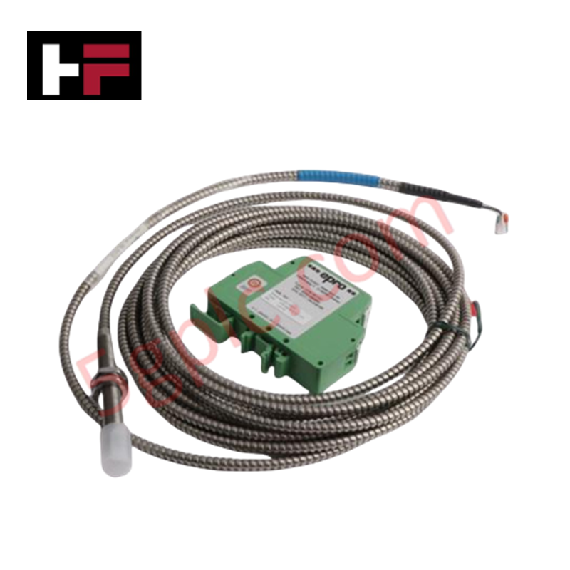
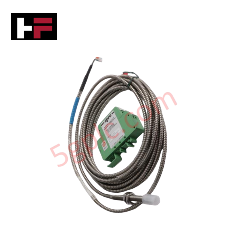
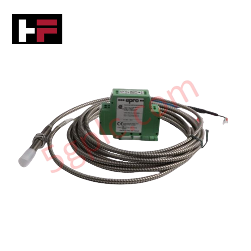
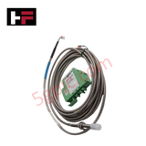
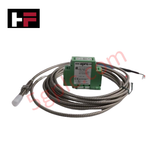
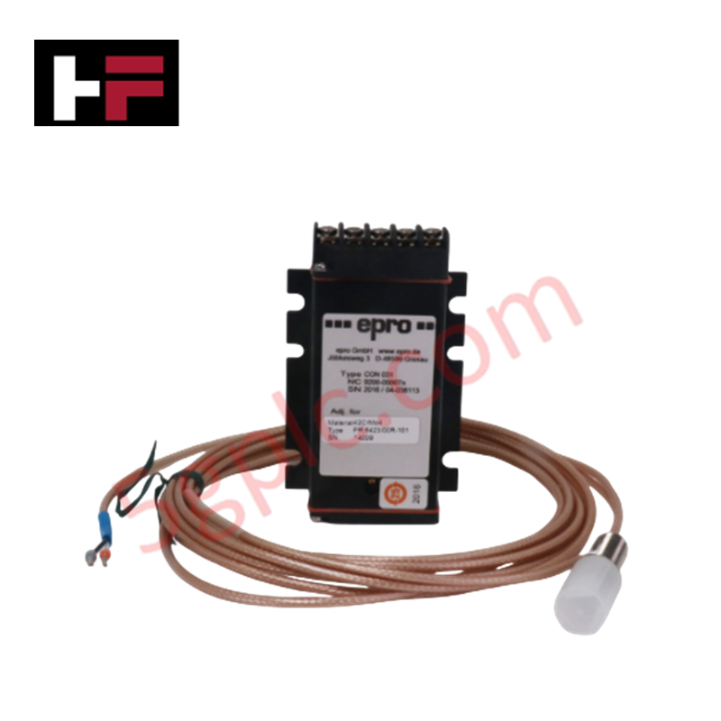
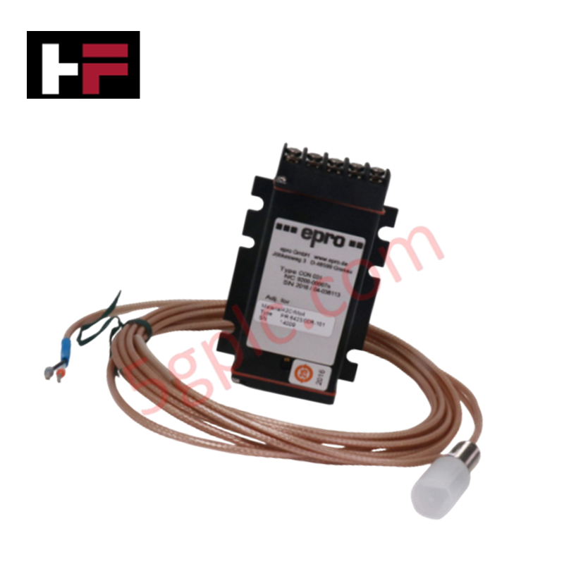
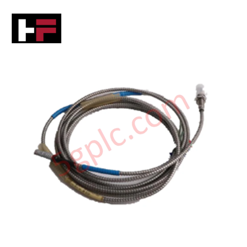
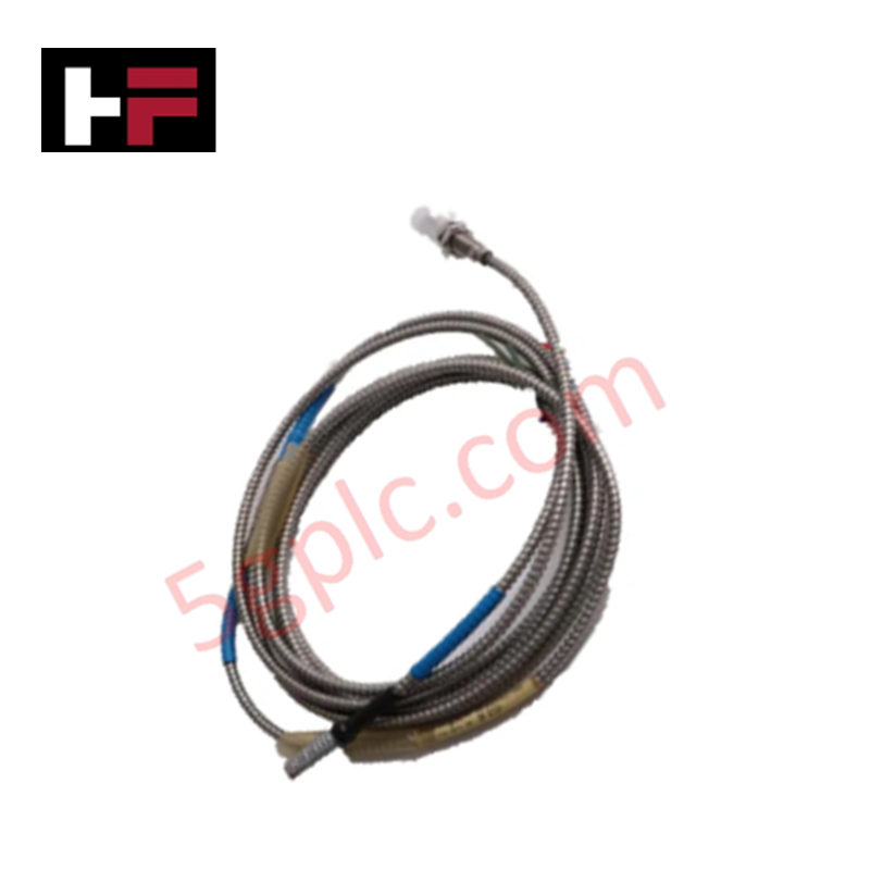
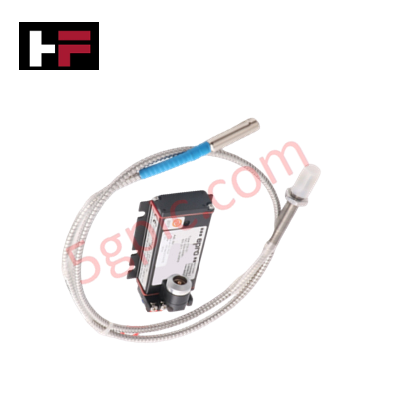
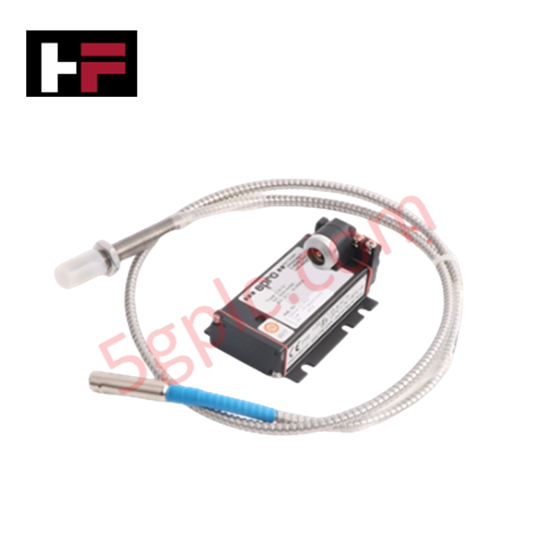
The Emerson EPRO CON010+PR6426/010-140, also cataloged as the CON010+PR6426/010-140 Eddy Current Sensor System, operates as a dedicated hardware component for non-contact shaft displacement measurement within turbomachinery monitoring systems.
Hardware Specifications
| Parameter | Specification |
|---|---|
| Model | CON010+PR6426/010-140 |
| Brand | Emerson EPRO |
| Base Model | CON010+PR6426/010-140 |
| Origin | Germany |
| Weight | Approx 1.4 kg |
| Dimensions | 32 mm sensor head diameter |
| Operating Temp | -35 to +180 deg C (short excursions up to +200 deg C) |
| Power Consumption | Powered via converter loop connection |
| System Components | PR6426 probe, extension cable, CON010 converter |
| Measurement Range | +/-4.0 mm (+/-0.157 in) |
| Linear Range | 0 to 20 mm |
| Sensitivity | 2 V/mm (50.8 mV/mil), +/-1.5% max |
| Accuracy | +/-0.1 mm |
| Repeatability | +/-0.05 mm |
| Target Material | Ferromagnetic steel (42CrMo4 / AISI 4140) |
| Target Limits | Min shaft diameter >=200 mm, max surface speed 2500 m/s |
| Connector Type | LEMO industrial-grade connector |
| Shock & Vibration | 5 g at 60 Hz, 25 deg C |
Eddy-Current Probe Scaling and Gap Voltage Validation
The CON010+PR6426/010-140 system relies on precise eddy-current probe scaling to convert high-frequency magnetic field alterations into standard analog voltage outputs. During physical setup, gap voltage validation targets nominal DC offset voltages to verify the uncalibrated mechanical clearance between the 32 mm probe tip and target shaft material. Proper zero-gap setup suppresses signal cross-talk and preserves a linear sensitivity of 2 V/mm across the entire +/-4.0 mm dynamic measurement range.
Frequently Asked Questions
Q: What components constitute the complete CON010+PR6426/010-140 system measurement chain?
A: The system consists of three matched physical components: the PR6426/010-140 non-contact probe head, an extension cable with LEMO industrial connectors, and the CON010 signal converter module.
Q: What are the thermal limits for the probe head during operation near hot turbine casings?
A: The probe head operates continuously within a temperature window of -35 to +180 deg C, with short-term thermal excursion tolerance up to +200 deg C.
Q: What target shaft parameters are required to maintain linear signal calibration?
A: Calibration requires a ferromagnetic steel target material (42CrMo4 / AISI 4140) with a minimum shaft diameter of 200 mm or greater.
Field Installation Guidelines
- Mount the 32 mm probe head into the machine casing bracket using calibrated threaded fixtures.
- Measure unpowered static physical gap and adjust probe depth until the signal output matches the required DC gap voltage baseline.
- Connect the probe lead to the CON010 converter using the LEMO extension cable, ensuring connectors are fully seated and protected from oil exposure.
- Route signal cables away from high-voltage motor leads and variable frequency drive wiring to prevent electromagnetic interference.
- Secure field wiring shields to a single-point system ground block at the monitoring rack end.
Additional Information
- 100% Genuine Parts: All products are original and authentic, ensuring reliable industrial performance.
- 30-Day Refund Guarantee: Return any in-stock item within 30 days in original, unopened packaging for a full refund (excluding shipping and fees).
- 12-Month Warranty: Covers defects in materials or workmanship; excludes misuse, normal wear, or unauthorized modifications.
- Worldwide Shipping: We ship via USPS, UPS, FedEx, and DHL. Delivery times vary by country and may be subject to customs or import fees.
- Support & Contact: Technical and warranty assistance is available anytime. Contact us here: Contact.
- Purchase Guidance: Check product specifications and compatibility carefully before ordering to ensure proper application.




Tech & Buying Guide

Understanding Modern SCADA Systems: Architecture, Communication Topologies, and Industrial Applications
Supervisory Control and Data Acquisition (SCADA) systems form the digital backbone of modern industrial automation. They collect critical field data, transmit signals across vast distances, and empower plant operators with real-time process visibility. Across modern infrastructures, SCADA solutions streamline centralized control and maintain continuous operational uptime.

Understanding OPC Servers in Modern Industrial Automation: Principles, Architecture, and Applications
In industrial automation, connecting physical hardware with high-level software remains a primary operational challenge. Factories utilize programmable logic controllers (PLCs), distributed control systems (DCS), human-machine interfaces (HMIs), and smart sensors from diverse vendors. These devices often speak different proprietary protocols. Open Platform Communications (OPC) servers solve this interoperability challenge by standardizing how data flows across factory networks.

Industrial Fiber Optic Cables: Principles, Connectors, and Fusion Splicing Techniques
Modern factory automation relies heavily on fiber optic cables for high-speed industrial data transmission. Fiber optic cables transmit light pulses instead of electrical signals, eliminating electromagnetic interference (EMI) risks completely. Each optical strand consists of a high-purity glass core surrounded by a protective cladding layer. The difference in refractive index between core and cladding enables total internal reflection. Protective resin buffers, Kevlar strength members, and rugged outer jackets safeguard delicate glass cores in harsh environments. Consequently, automation engineers prefer fiber backbones for reliable noise-free communication in industrial control systems.