


Product Details
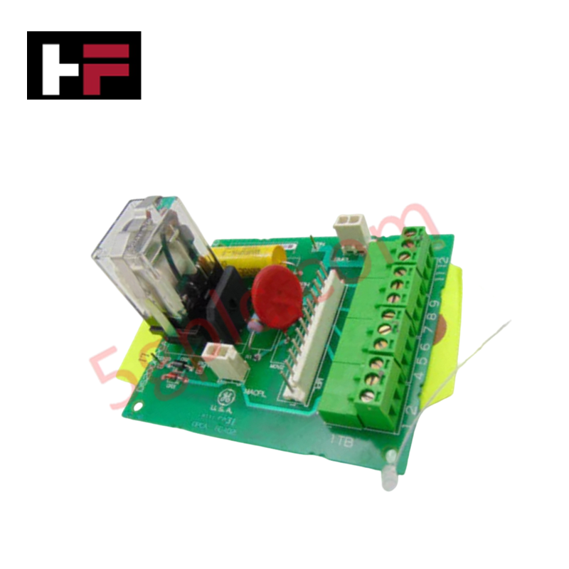
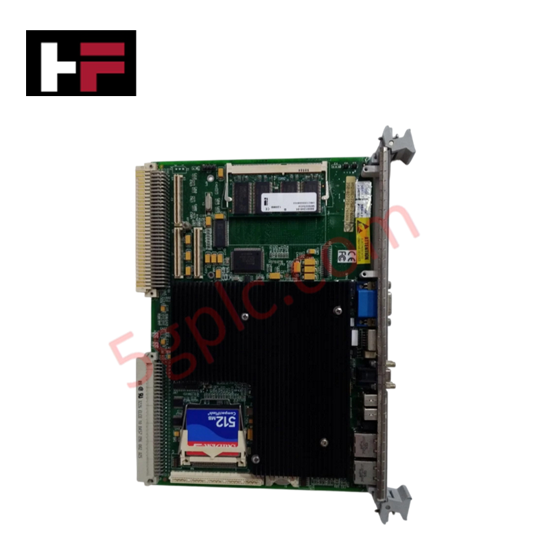
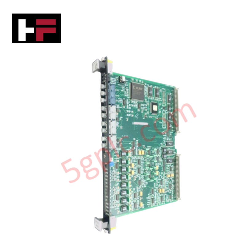
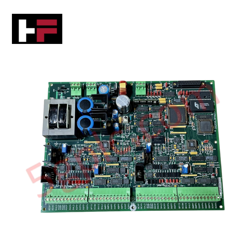
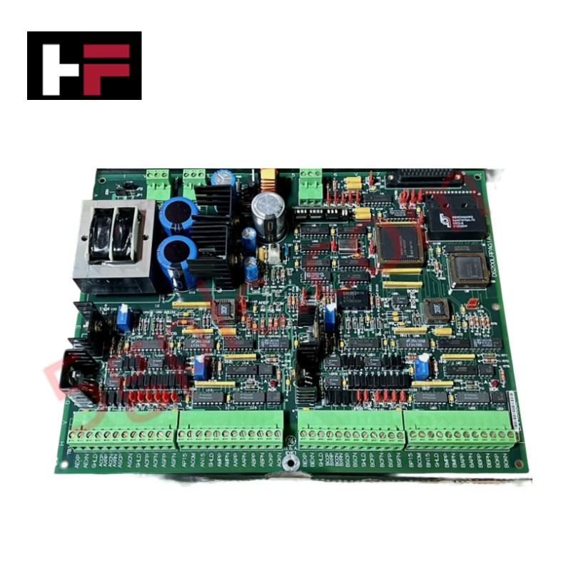
Configured for contactor control and excitation management in EX2000 systems, the GE DS200CPCAG1A (DS200CPCA Contactor Pilot Board) provides direct physical/electrical execution of coil switching sequences.
Hardware Specifications
| Parameter | Specification |
|---|---|
| Model | DS200CPCAG1A |
| Brand | GE (General Electric) |
| Origin | USA |
| Weight | 0.45 kg |
| Dimensions | 23.8 cm x 8.6 cm |
| Operating Temp | -35 to 65 deg C |
| Power Consumption | 25 VDC (Control Logic) |
| Input Voltage | 115 VAC |
| Output Voltage | 105 VDC (Contactor Coil Drive) |
PLC/DCS Deterministic Network Integration
The DS200CPCAG1A manages contactor state transitions by rectifying 115 VAC input into 105 VDC output for coil actuation. Integration into the EX2000 system requires precise coordination with the existing backplane bus communication velocity. As a critical link in the excitation sequence, this board maintains deterministic timing during state changes, ensuring that coil voltage is sustained to keep the contactor closed. Firmware flash compatibility and hardware handshaking protocols must be verified against the host controller revision to prevent timing latencies during high-frequency switching operations.
Frequently Asked Questions
Q: Can the test points CPH and CPN be measured with standard grounded multimeters?
A: No. CPH and CPN are not referenced to the drive's common level. All measurements must be performed using isolated test equipment capable of measuring floating potentials to prevent circuit damage or ground fault conditions.
Q: How does the CPCA functionality differ from the CDBA board in terms of load handling?
A: While the CDBA board initiates the electricity for contactor operation, the CPCA board provides the full voltage required to close and maintain the contactor in a closed state, assuming the primary load responsibilities for the coil drive.
Field Installation Guidelines
- Mounting: Ensure the board is securely seated in the designated EX2000 cabinet slot using the provided guide rails. Verify mechanical clearance for the 23.8 cm x 8.6 cm footprint.
- Wiring: Use appropriate gauge wire for the 115 VAC input connections. Ensure all terminals are tightened to specified torque values to prevent high-resistance connections and overheating during continuous coil activation.
- Grounding and Shielding: Ensure the cabinet chassis is properly earth-grounded. Because the board handles AC-to-DC conversion for inductive loads, maintain physical separation between signal cables and high-power conductors to mitigate electromagnetic interference.
- Testing: Before applying full system power, perform continuity checks using isolated equipment at the designated test points (CPH, CPN, PSP, PSN) to verify correct voltage polarity and conversion levels.
Additional Information
- 100% Genuine Parts: All products are original and authentic, ensuring reliable industrial performance.
- 30-Day Refund Guarantee: Return any in-stock item within 30 days in original, unopened packaging for a full refund (excluding shipping and fees).
- 12-Month Warranty: Covers defects in materials or workmanship; excludes misuse, normal wear, or unauthorized modifications.
- Worldwide Shipping: We ship via USPS, UPS, FedEx, and DHL. Delivery times vary by country and may be subject to customs or import fees.
- Support & Contact: Technical and warranty assistance is available anytime. Contact us here: Contact.
- Purchase Guidance: Check product specifications and compatibility carefully before ordering to ensure proper application.
Tech & Buying Guide

Essential SCADA Features for Modern IoT-Enabled Industrial Automation
The convergence of traditional SCADA systems with the Industrial Internet of Things (IIoT) has redefined factory automation. Choosing a robust platform requires more than just standard monitoring capabilities. In this era of Industry 4.0, your supervisory system must bridge the gap between legacy control systems and enterprise-level data integration.

Selecting Rockwell Automation Allen-Bradley PLCs for Small and Mid-Sized Applications
Rockwell Automation remains a cornerstone in global industrial automation. Their Allen-Bradley brand provides a comprehensive portfolio of control systems designed to meet diverse production requirements. Choosing the right programmable logic controller (PLC) is critical for system reliability and scalability. This guide analyzes the Micro and Compact Logix families to help you select the optimal solution for small and medium-scale projects.

Strategic Selection: Choosing the Right SCADA Software for Your PLC Project
In industrial automation, the SCADA (Supervisory Control and Data Acquisition) system acts as the bridge between raw machine data and actionable human intelligence. Selecting the incorrect software platform can lead to integration bottlenecks, scalability issues, and excessive long-term maintenance costs. As an automation consultant with 15 years of experience, I have guided many projects through the selection process. Below are the essential criteria for choosing a platform that ensures both performance and longevity.