


Product Details
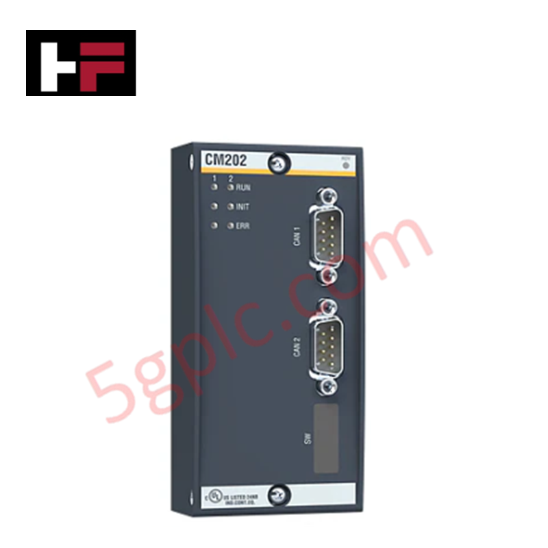
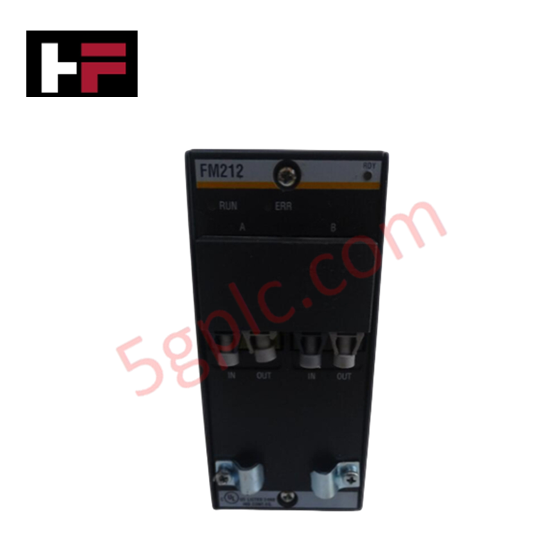
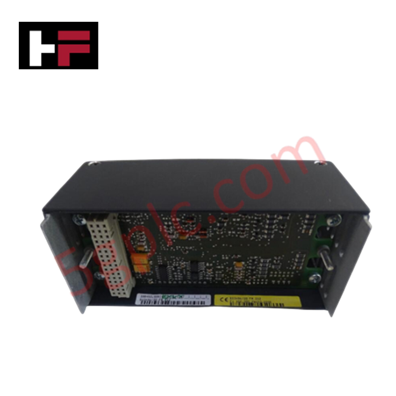
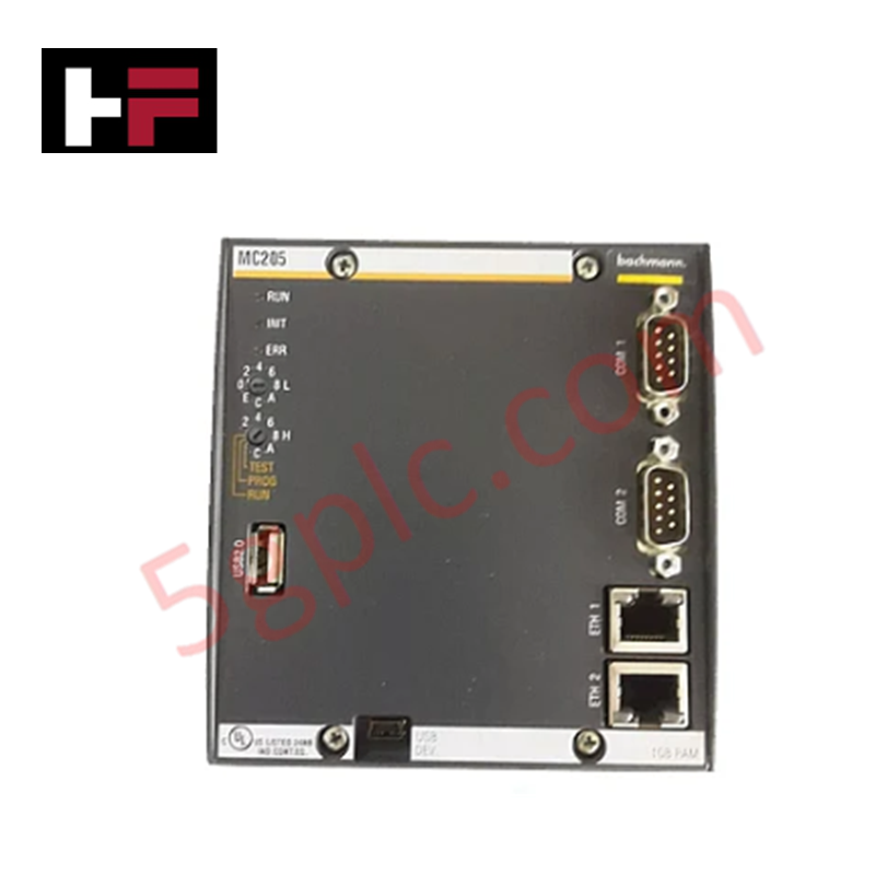
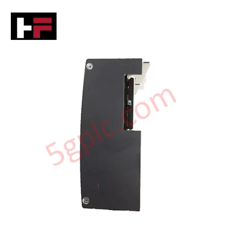
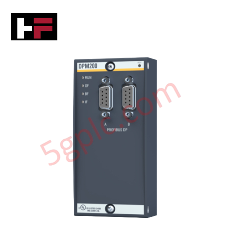
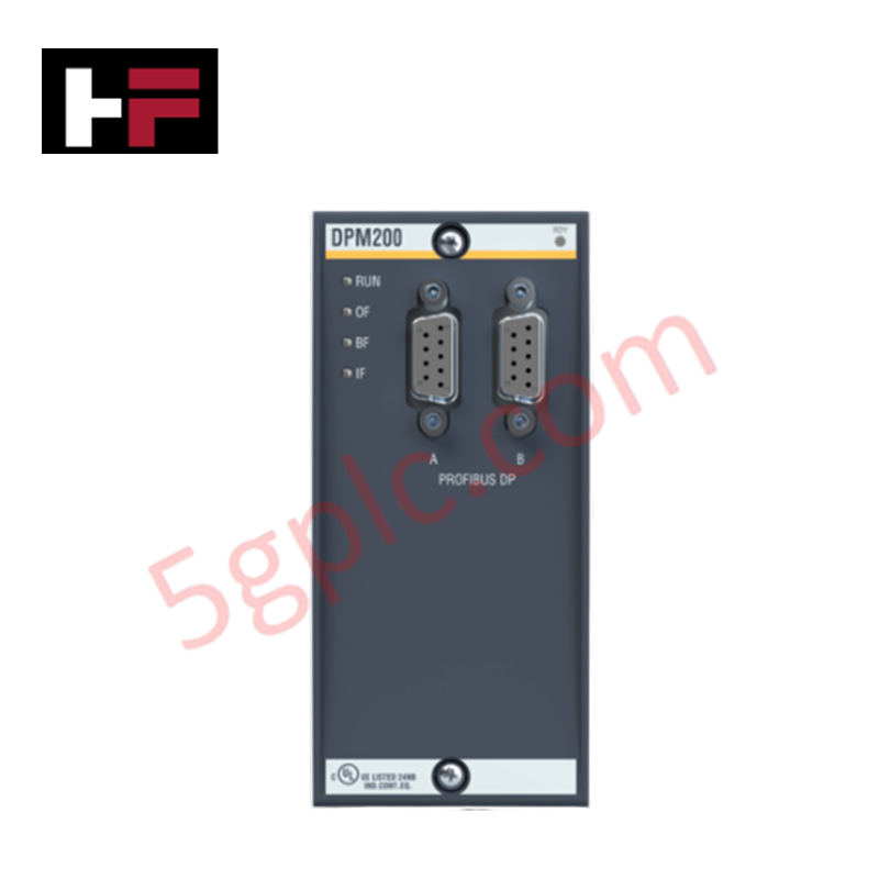
Configured for high-speed fieldbus communication in M1 automation platforms, the BACHMANN CM202 (CM202 CANopen Master Module) provides direct physical/electrical execution of CAN network management and data telegram routing.
Hardware Specifications
| Parameter | Specification |
|---|---|
| Model | CM202 |
| Brand | BACHMANN |
| Origin | Austria |
| Weight | 0.22 kg |
| Dimensions | 5.4 cm x 5.5 cm x 11.8 cm |
| Operating Temp | -20 deg C to 60 deg C (typical) |
| Power Consumption | 2.5 W (typical) |
| Max Modules per Controller | 4 |
| Network Protocols | Node Guarding, Heartbeat |
| Transfer Rate | 10 Kbaud to 1 Mbaud |
| Electrical Isolation | Galvanically isolated |
Backplane Bus Communication and Network Determinism
The CM202 module utilizes the Bachmann M1 backplane bus communication velocity to synchronize CANopen data packets with the controller execution cycle. Each module supports up to 8 independent CAN networks per controller, with operation modes configured on a per-network basis. The module handles SDO, LMT, LSS, and emergency message processing via an extensive API. Network deterministic performance is maintained through strict timing controls, with maximum node counts and cable lengths governed by the selected baud rate to minimize bus latency and collision overhead.
Frequently Asked Questions
Q: Does the CM202 support hot-swapping while the controller is operational?
A: No, the module does not support live hot-swapping; the controller power must be cycled or the specific bus segment must be offlined to ensure system bus integrity during installation.
Q: How does the CM202 ensure electrical protection against bus faults?
A: The module is designed with galvanic isolation for all field connections and includes short-circuit-proof outputs to prevent localized bus faults from propagating to the controller backplane.
Q: Can multiple CM202 modules operate concurrently on a single M200 controller?
A: Yes, up to 4 CM202 modules can be installed on a single M200 controller, supporting a total of up to 8 independent CAN networks.
Field Installation Guidelines
- Bus Termination: Ensure that 120 Ohm terminating resistors are installed at both extreme ends of the CAN bus trunk to prevent signal reflections and data corruption.
- Cable Shielding: Utilize twisted-pair shielded cabling for all CAN network segments. Connect the cable shield to a high-frequency earth potential at the entry point of the control cabinet to minimize electromagnetic interference (EMI).
- Grounding: Verify that the module's functional earth connection is secure to maintain the effectiveness of the galvanic isolation barrier.
- Wiring Topology: Maintain a daisy-chain topology for the CAN network; avoid long stubs or T-connections to prevent signal degradation at higher baud rates (above 500 Kbaud).
Additional Information
- 100% Genuine Parts: All products are original and authentic, ensuring reliable industrial performance.
- 30-Day Refund Guarantee: Return any in-stock item within 30 days in original, unopened packaging for a full refund (excluding shipping and fees).
- 12-Month Warranty: Covers defects in materials or workmanship; excludes misuse, normal wear, or unauthorized modifications.
- Worldwide Shipping: We ship via USPS, UPS, FedEx, and DHL. Delivery times vary by country and may be subject to customs or import fees.
- Support & Contact: Technical and warranty assistance is available anytime. Contact us here: Contact.
- Purchase Guidance: Check product specifications and compatibility carefully before ordering to ensure proper application.
Tech & Buying Guide

Strategic Selection: Choosing the Right SCADA Software for Your PLC Project
In industrial automation, the SCADA (Supervisory Control and Data Acquisition) system acts as the bridge between raw machine data and actionable human intelligence. Selecting the incorrect software platform can lead to integration bottlenecks, scalability issues, and excessive long-term maintenance costs. As an automation consultant with 15 years of experience, I have guided many projects through the selection process. Below are the essential criteria for choosing a platform that ensures both performance and longevity.

Ensuring Operational Continuity: The Strategic Value of Redundant Automation Systems
In modern industrial landscapes, unplanned downtime is the ultimate adversary. For sectors relying on complex PLC and DCS architectures, a single hardware failure can trigger catastrophic production losses. Therefore, implementing redundant automation systems is no longer a luxury; it is a fundamental requirement for mission-critical operations. In this article, I analyze why redundancy remains the backbone of reliable industrial infrastructure.

Selecting the Right Cables for Industrial Automation: A Comprehensive Guide
Selecting the appropriate cabling infrastructure is critical for the success of any industrial automation project. Improper cable selection often leads to signal degradation, system instability, and costly downtime. As an automation engineer, I frequently see projects compromised by poor cabling choices in harsh industrial environments. This guide simplifies the complex landscape of cabling to help you make informed decisions for your PLC, DCS, and control systems.