


Product Details
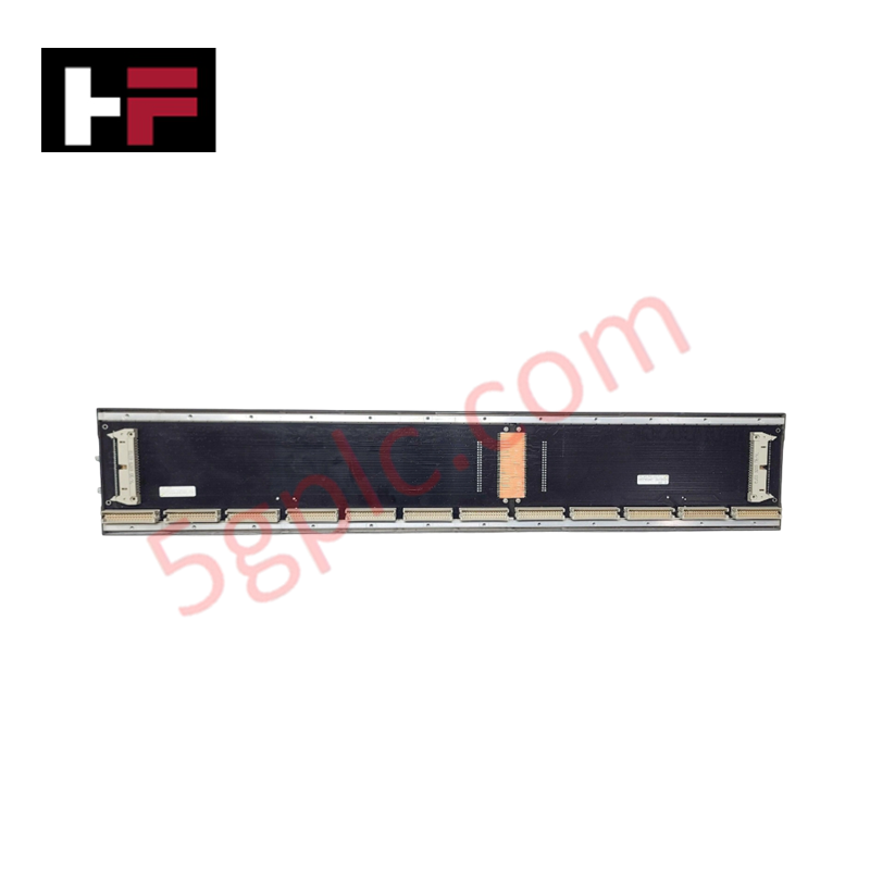
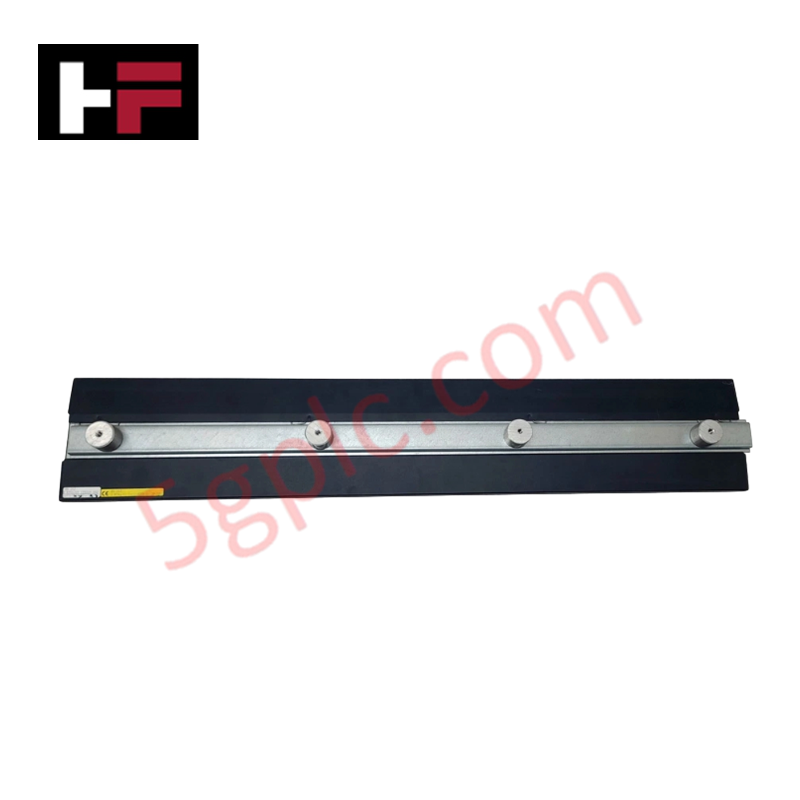
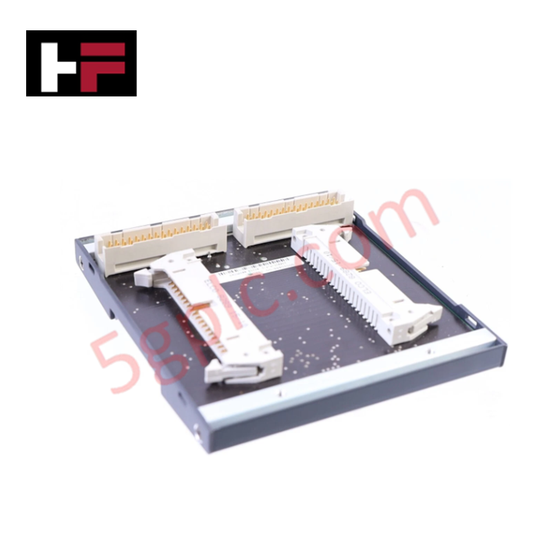
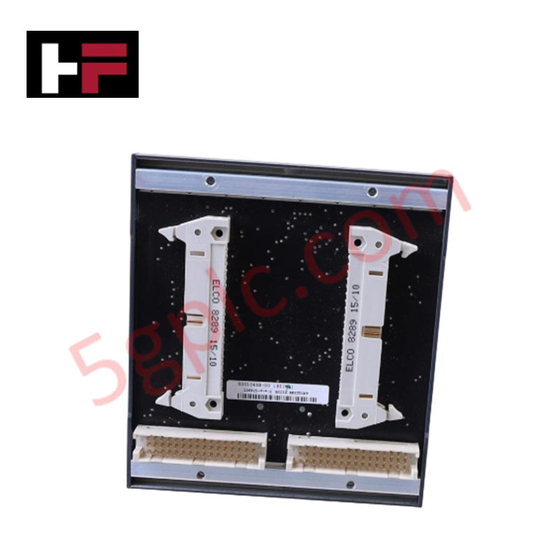
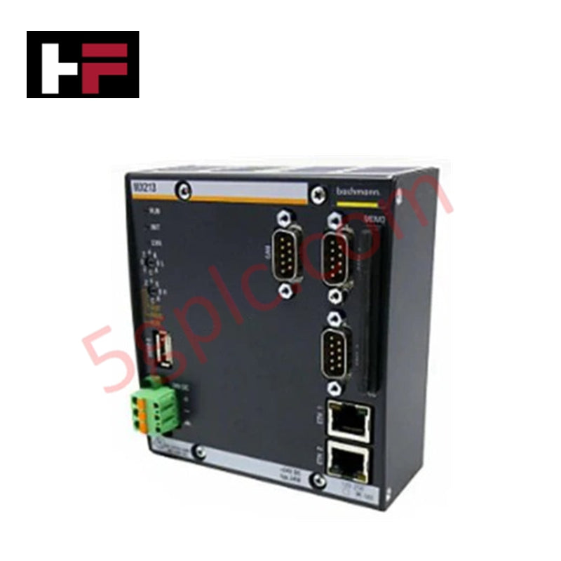
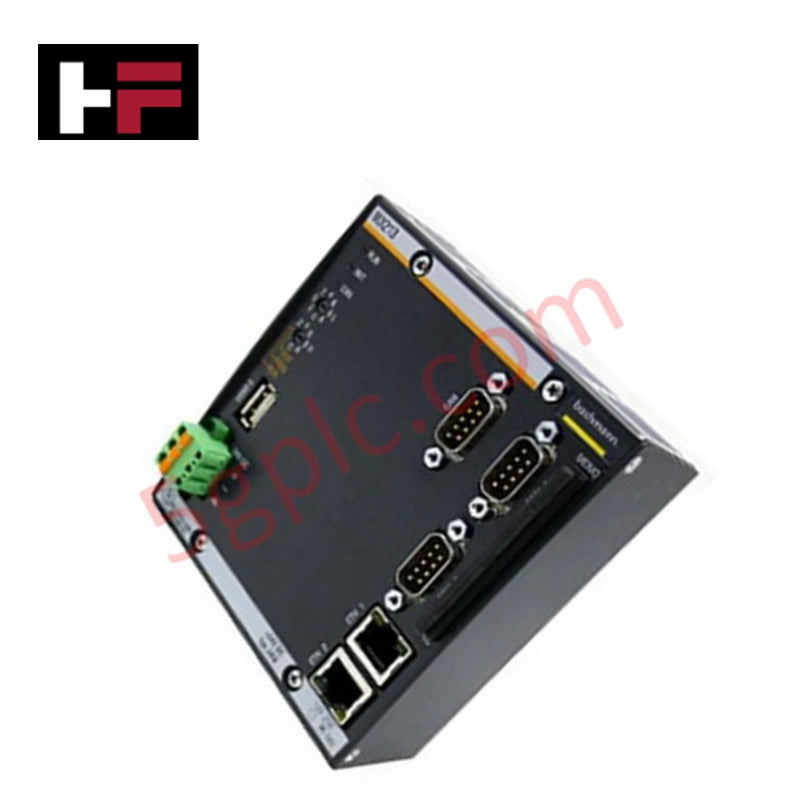
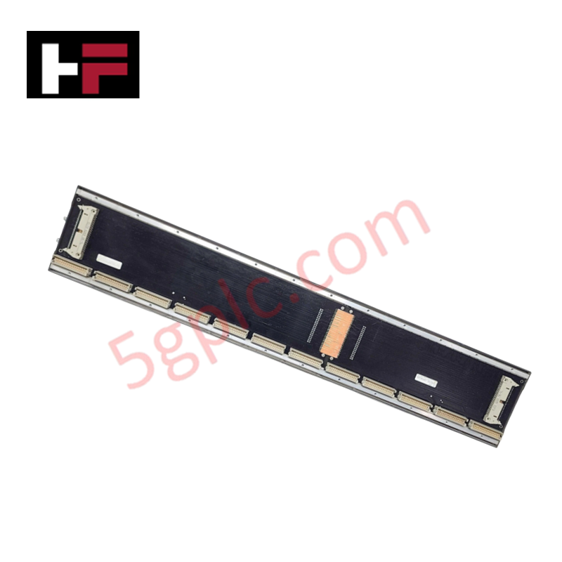
Configured for mechanical and electrical interconnection in M1 automation platforms, the Bachmann BS212 (BS212 Backplane) provides direct signal and power distribution across 12 module slots.
Hardware Specifications
| Parameter | Specification |
|---|---|
| Model | BS212 |
| Brand | Bachmann |
| Origin | Austria |
| Dimensions | Standard 12-slot enclosure geometry |
| Operating Temp | -30 deg C to +60 deg C |
| Power Consumption | Passive distribution |
| Slots | 12 slots |
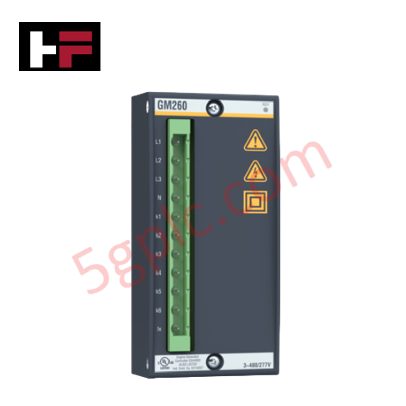
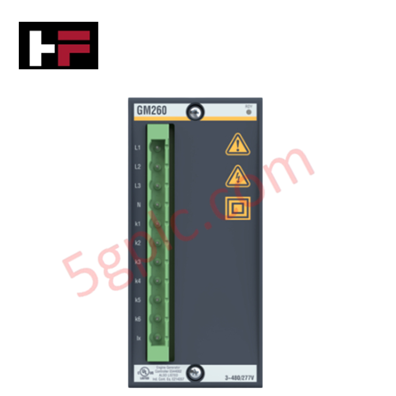
| Connection Type | Spring clamp or screw terminals |
| Wire Size | 0.25 mm2 to 2.5 mm2 |
Backplane Bus Communication Velocity Licences
The BS212 backplane serves as the physical foundation for the Bachmann M1 system, facilitating the high-speed data transfer required for deterministic control. The internal bus structure is optimized to support the high-velocity communication protocols required by modern CPU and I/O modules. To maintain deterministic synchronization across all 12 slots, users must ensure that the total bus load does not exceed the power distribution limits defined by the system configuration. Firmware flash compatibility across modules is inherently supported by the backplane physical layer, provided that electrical continuity is maintained through secure terminal connections and proper grounding of the protective conductor tab.
Frequently Asked Questions
Q: Does the BS212 support expansion via additional backplanes?
A: Yes, the BS212 is designed to be expandable. Multiple backplanes can be interconnected to increase the total number of available slots, provided the system power supply and bus communication bandwidth are within the specified operational limits.
Q: Is grounding required for this backplane?
A: A grounding tab for the protective conductor is provided and is required when non-SELV (Safety Extra Low Voltage) signals are present on the backplane, ensuring compliance with industrial electrical safety standards.
Field Installation Guidelines
- Mount the backplane using a snap-on EN 60715 DIN rail or panel mount method. Ensure the mechanical interface is rigid to prevent stress on the internal bus connectors.
- Terminate field wiring using the appropriate spring clamp or screw terminal variant, ensuring wire gauges are within the 0.25 mm2 to 2.5 mm2 range.
- Verify that the protective conductor (grounding tab) is properly bonded to the system chassis ground to mitigate potential difference issues.
- Ensure all modules are fully seated in their respective slots to establish positive contact with the internal bus pins.
- In environments with high humidity (5% to 95%, non-condensing), ensure the cabinet environment remains controlled to prevent condensation-related short circuits on the exposed backplane traces.
Additional Information
- 100% Genuine Parts: All products are original and authentic, ensuring reliable industrial performance.
- 30-Day Refund Guarantee: Return any in-stock item within 30 days in original, unopened packaging for a full refund (excluding shipping and fees).
- 12-Month Warranty: Covers defects in materials or workmanship; excludes misuse, normal wear, or unauthorized modifications.
- Worldwide Shipping: We ship via USPS, UPS, FedEx, and DHL. Delivery times vary by country and may be subject to customs or import fees.
- Support & Contact: Technical and warranty assistance is available anytime. Contact us here: Contact.
- Purchase Guidance: Check product specifications and compatibility carefully before ordering to ensure proper application.

Tech & Buying Guide

Strategic Selection: Choosing the Right SCADA Software for Your PLC Project
In industrial automation, the SCADA (Supervisory Control and Data Acquisition) system acts as the bridge between raw machine data and actionable human intelligence. Selecting the incorrect software platform can lead to integration bottlenecks, scalability issues, and excessive long-term maintenance costs. As an automation consultant with 15 years of experience, I have guided many projects through the selection process. Below are the essential criteria for choosing a platform that ensures both performance and longevity.

Ensuring Operational Continuity: The Strategic Value of Redundant Automation Systems
In modern industrial landscapes, unplanned downtime is the ultimate adversary. For sectors relying on complex PLC and DCS architectures, a single hardware failure can trigger catastrophic production losses. Therefore, implementing redundant automation systems is no longer a luxury; it is a fundamental requirement for mission-critical operations. In this article, I analyze why redundancy remains the backbone of reliable industrial infrastructure.

Selecting the Right Cables for Industrial Automation: A Comprehensive Guide
Selecting the appropriate cabling infrastructure is critical for the success of any industrial automation project. Improper cable selection often leads to signal degradation, system instability, and costly downtime. As an automation engineer, I frequently see projects compromised by poor cabling choices in harsh industrial environments. This guide simplifies the complex landscape of cabling to help you make informed decisions for your PLC, DCS, and control systems.