


Product Details
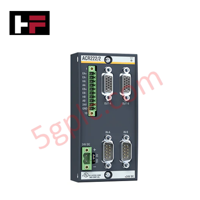
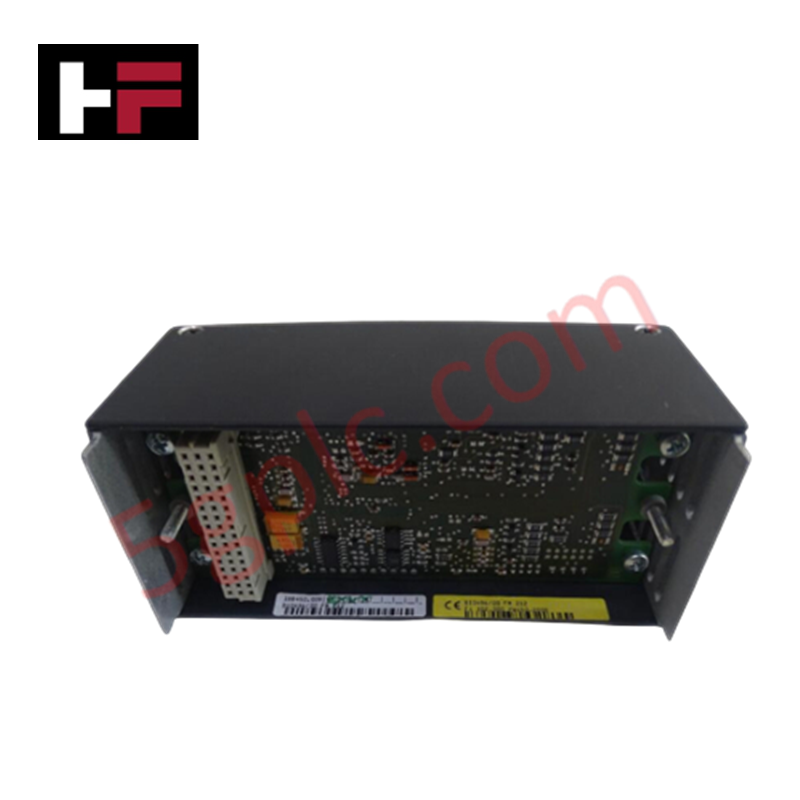
Configured for high-speed motion control in M1 automation platforms, the BACHMANN ACR222/2 (ACR222/2 Axis Controller Module) provides direct physical/electrical execution of stepper motor driving and incremental encoder signal processing.
Hardware Specifications
| Parameter | Specification |
|---|---|
| Model | ACR222/2 |
| Brand | BACHMANN |
| Origin | Austria |
| Weight | 0.28 kg |
| Dimensions | 102 mm x 12 mm x 130 mm |
| Operating Temp | 0 deg C to 60 deg C |
| Power Consumption | 4.0 W |
| Stepper Interfaces | 2 channels, up to 150 kHz |
| Encoder Interfaces | 2 channels, up to 1 MHz |
| Digital Inputs | Home, Abort, 2 Limit switches per channel |
| Profile Types | Linear, sin2, parabolic |
Profinet / EtherNet/IP Deterministic Networks
The ACR222/2 integrates into the M1 backplane architecture to ensure synchronization between motion profiles and system-level bus communication. The module supports deterministic network connectivity, allowing for real-time adjustments of velocity profiles via the controller CPU. I/O density scaling is managed through the M1 modular backplane, enabling the expansion of axis control nodes without degrading the bus communication velocity. Firmware flash compatibility is supported, ensuring the motion control algorithms, including the two-step linear speed profiles, can be updated to meet specific mechanical kinematics requirements.
Frequently Asked Questions
Q: Can the ACR222/2 provide power directly to the connected incremental encoders?
A: Yes, the module provides an integrated encoder power supply directly through the front-panel connectors to simplify field wiring.
Q: What is the maximum step frequency supported for the stepper motor output stages?
A: The module supports stepper frequencies up to 150 kHz per interface.
Q: Does the module perform hardware-level monitoring of the connected motor stages?
A: Yes, the module includes monitoring circuitry for the external supplying voltage and supports physical limit switch inputs to ensure operation within configured mechanical boundaries.
Field Installation Guidelines
- Connector Wiring: Utilize shielded twisted-pair cables for both encoder feedback and stepper motor signals. Connect cable shields to the system functional earth (FE) terminal to prevent electrical noise interference at the 1 MHz frequency range.
- Signal Segregation: Route high-frequency stepper motor pulse signals away from sensitive analog input cables and power wiring to mitigate potential cross-talk.
- Grounding: Ensure a low-impedance ground connection for the M1 rack to maintain signal integrity for the high-speed pulse outputs.
- Switch Configuration: Verify proper installation and NC/NO logic settings for home, abort, and limit switches during initial commissioning to prevent mechanical overtravel.
Additional Information
- 100% Genuine Parts: All products are original and authentic, ensuring reliable industrial performance.
- 30-Day Refund Guarantee: Return any in-stock item within 30 days in original, unopened packaging for a full refund (excluding shipping and fees).
- 12-Month Warranty: Covers defects in materials or workmanship; excludes misuse, normal wear, or unauthorized modifications.
- Worldwide Shipping: We ship via USPS, UPS, FedEx, and DHL. Delivery times vary by country and may be subject to customs or import fees.
- Support & Contact: Technical and warranty assistance is available anytime. Contact us here: Contact.
- Purchase Guidance: Check product specifications and compatibility carefully before ordering to ensure proper application.
Tech & Buying Guide

Strategic Selection: Choosing the Right SCADA Software for Your PLC Project
In industrial automation, the SCADA (Supervisory Control and Data Acquisition) system acts as the bridge between raw machine data and actionable human intelligence. Selecting the incorrect software platform can lead to integration bottlenecks, scalability issues, and excessive long-term maintenance costs. As an automation consultant with 15 years of experience, I have guided many projects through the selection process. Below are the essential criteria for choosing a platform that ensures both performance and longevity.

Ensuring Operational Continuity: The Strategic Value of Redundant Automation Systems
In modern industrial landscapes, unplanned downtime is the ultimate adversary. For sectors relying on complex PLC and DCS architectures, a single hardware failure can trigger catastrophic production losses. Therefore, implementing redundant automation systems is no longer a luxury; it is a fundamental requirement for mission-critical operations. In this article, I analyze why redundancy remains the backbone of reliable industrial infrastructure.

Selecting the Right Cables for Industrial Automation: A Comprehensive Guide
Selecting the appropriate cabling infrastructure is critical for the success of any industrial automation project. Improper cable selection often leads to signal degradation, system instability, and costly downtime. As an automation engineer, I frequently see projects compromised by poor cabling choices in harsh industrial environments. This guide simplifies the complex landscape of cabling to help you make informed decisions for your PLC, DCS, and control systems.