


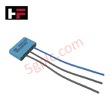
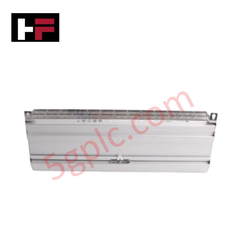
Product Details
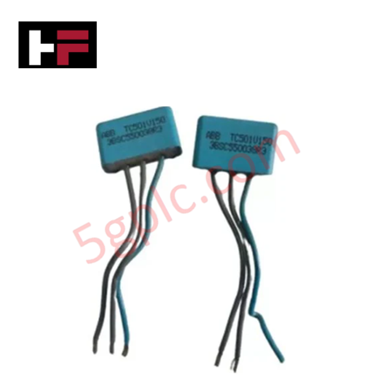
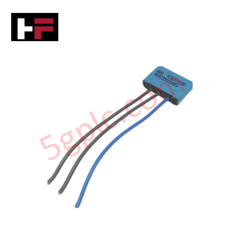
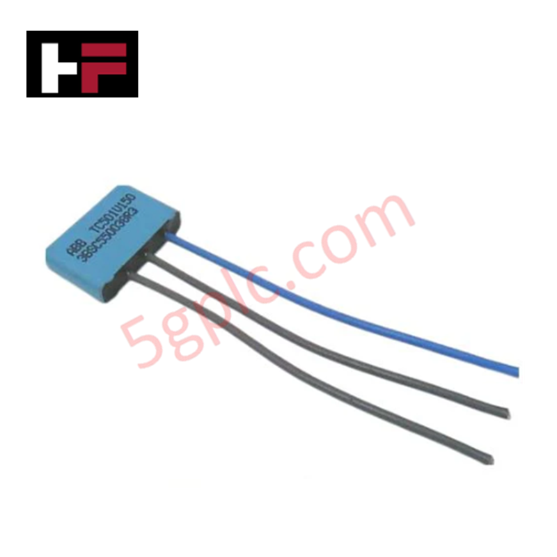
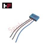
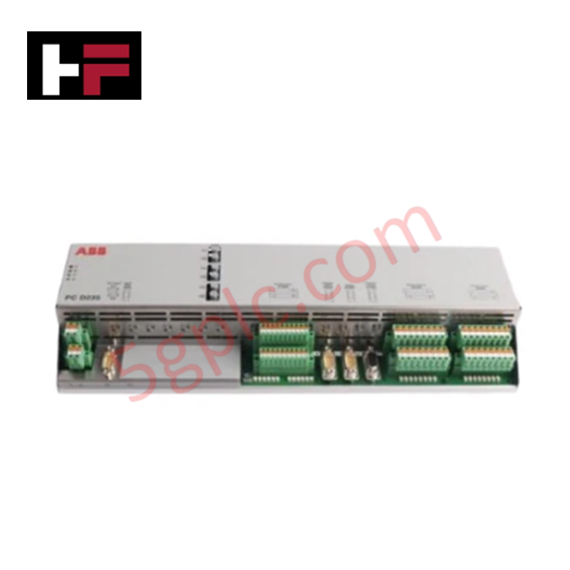
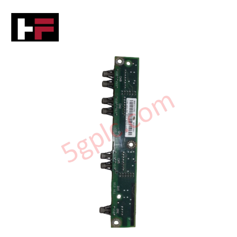
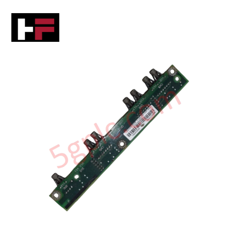
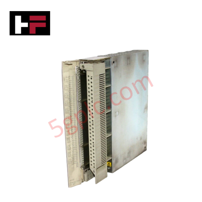
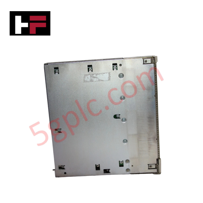
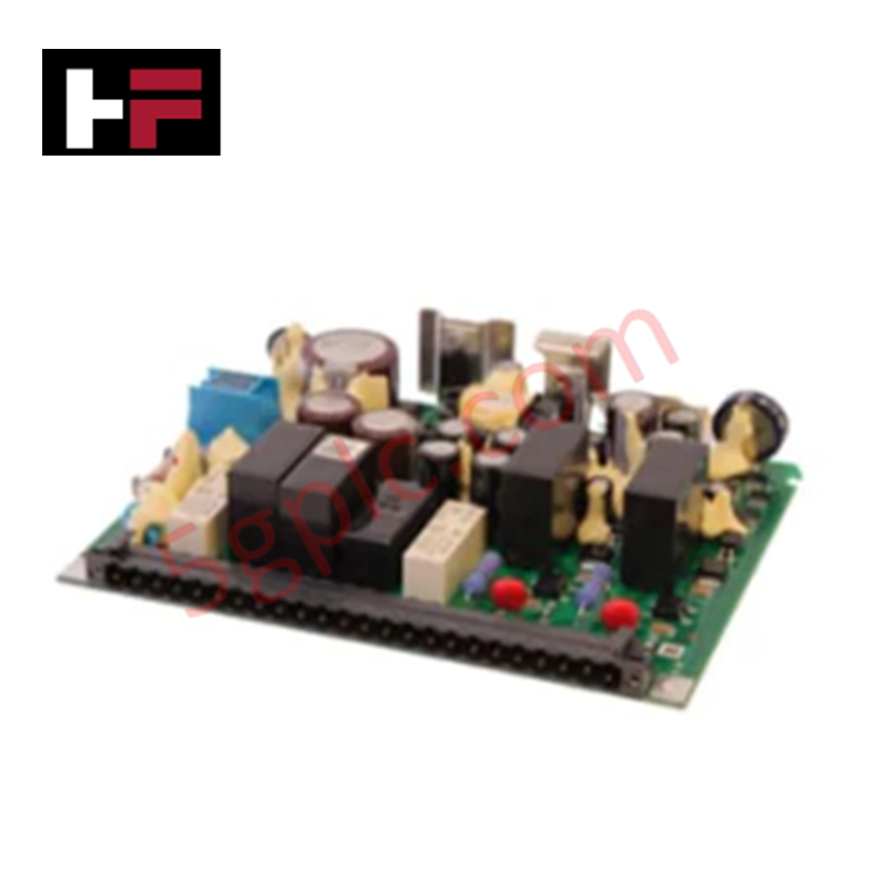
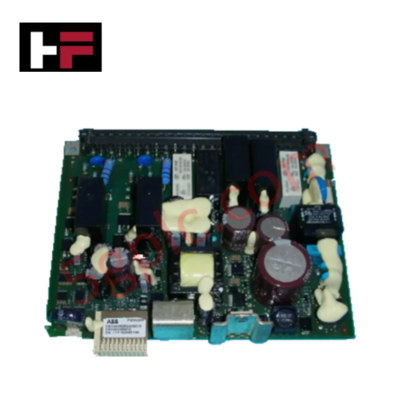
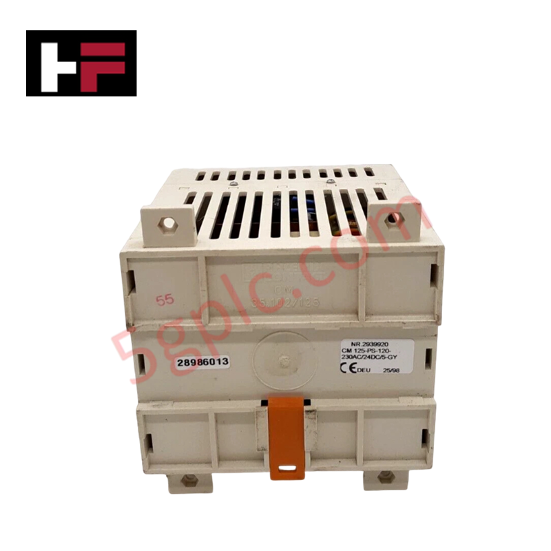
The ABB TC501V150 3BSC550038R3, also cataloged as the TC501V150 Termination Unit, operates as a dedicated hardware component for high-speed frequency processing and rotational speed acquisition within S600 I/O controller platforms.
Hardware Specifications
| Parameter | Specification |
|---|---|
| Model | TC501V150 3BSC550038R3 |
| Brand | ABB |
| Origin | Sweden / Europe standard sourcing |
| Weight | 0.005 kg net |
| Dimensions | 200 mm x 30 mm x 100 mm (W x H x D) |
| Operating Temp | 0 to 60 deg C |
| Power Consumption | Backplane logic bus and external 24 VDC loop dependent |
| Product Type | Termination Units |
| Speed Input Range | Max 50 kHz |
| Signal Thresholds | +/- 13 mA current limit; 24 VDC or 5 VDC configurations |
| Direction Detection | Executed through discrete secondary sensor channel pairing |
| Trip Signal Interfaces | Solid-state 24 VDC output and dry contact 60 VDC output |
| Physical Isolation | Opto-isolated speed inputs and solid-state output circuits |
Deterministic Network Routing and I/O Density Scaling
The ABB TC501V150 3BSC550038R3 implements dedicated onboard hardware elements to process sub-millisecond frequency dynamics without affecting overall backplane bus communication velocity. The opto-isolated frequency channels enable rapid pulse counting up to 50 kHz, running deterministic speed and overspeed trip logic calculation loops outside the primary application processor task cycle. This dedicated regional processing capability supports dense I/O density scaling routines across the local backplane segment, preventing timing jitter and ensuring full firmware flash compatibility with upstream S600 master automation controllers.
Frequently Asked Questions
Q: How does the hardware handle rotational direction validation?
A: Direction detection is processed electronically by matching the phase relationship between the primary speed input and the secondary hardware speed meter channel.
Q: Can the overspeed trip circuits be modified or hot-swapped while the active controller loop is running?
A: Removing the termination unit while active will immediately break the pulse acquisition loop and open the 60 VDC dry contact safety circuit, initiating an immediate fault state in the host system logic.
Field Installation Guidelines
- Mount the termination unit horizontally on its designated chassis or panel track layout to ensure natural air convection across the structural assembly.
- Ground all incoming speed sensor cables using a continuous, low-impedance shield clamp connected directly to the master copper bus bar.
- Separate the 50 kHz pulse input lines from parallel AC power cables or high-voltage inductive switching paths to mitigate electromagnetic interference.
- Verify the nominal sensor excitation loop matches the configured 24 VDC or 5 VDC hardware threshold limits before delivering field current.
Additional Information
- 100% Genuine Parts: All products are original and authentic, ensuring reliable industrial performance.
- 30-Day Refund Guarantee: Return any in-stock item within 30 days in original, unopened packaging for a full refund (excluding shipping and fees).
- 12-Month Warranty: Covers defects in materials or workmanship; excludes misuse, normal wear, or unauthorized modifications.
- Worldwide Shipping: We ship via USPS, UPS, FedEx, and DHL. Delivery times vary by country and may be subject to customs or import fees.
- Support & Contact: Technical and warranty assistance is available anytime. Contact us here: Contact.
- Purchase Guidance: Check product specifications and compatibility carefully before ordering to ensure proper application.
Tech & Buying Guide

Industrial PC vs. Commercial PC: Selecting the Right Hardware for Automation
In the demanding world of factory automation, selecting the correct computing platform is critical for system reliability. While commercial PCs power our daily lives, they often fail when subjected to the harsh realities of the production floor. Understanding the fundamental differences between an Industrial PC (IPC) and a standard office PC helps engineers optimize control systems for longevity and performance.

Core Components of Programmable Logic Controllers (PLC) in Industrial Automation
A Programmable Logic Controller (PLC) serves as the digital backbone of modern factory automation. Whether you are managing complex assembly lines or simple process loops, understanding the hardware and software architecture of a PLC is essential for any control systems engineer.

PLC vs. PC: Navigating the Architectural Differences in Industrial Automation
In the realm of factory automation, professionals often debate the roles of Programmable Logic Controllers (PLCs) and Personal Computers (PCs). While both devices share fundamental computing architectures—including a processor, memory, and an operating system—their design philosophies diverge significantly. Understanding these distinctions is critical for selecting the right hardware for your industrial control systems.