










Product Details
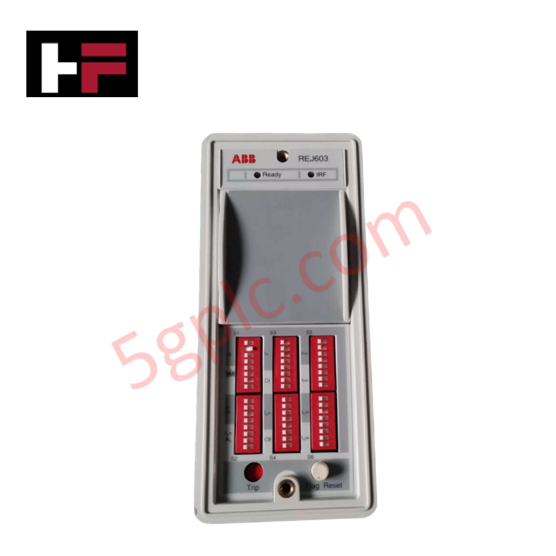
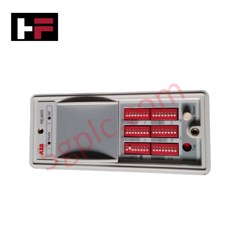
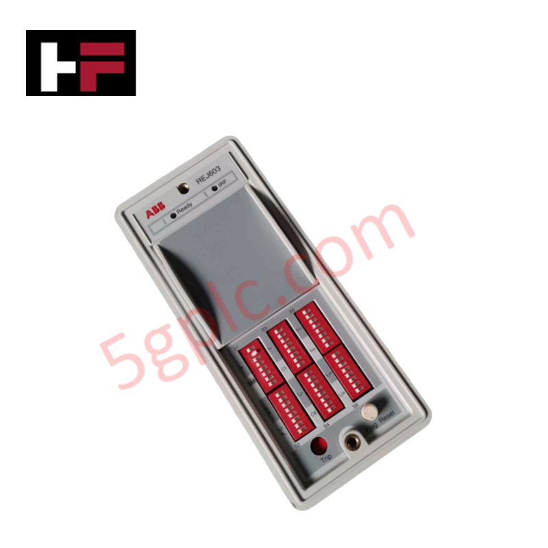
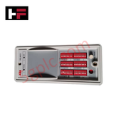
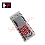
Configured for selective short-circuit and earth-fault measurement in secondary distribution networks, the ABB REJ603BBB1ONN3XB (REJ603 Self-Powered Feeder Protection Relay) provides direct physical/electrical execution. The device derives its full operating excitation current directly from the secondary loops of the main current transformers, eliminating dependency on external auxiliary power infrastructure to run its internal measuring, processing, and tripping circuits.
Hardware Specifications
| Parameter | Specification |
|---|---|
| Model | REJ603BBB1ONN3XB |
| Brand | ABB |
| Origin | India / Finland |
| Power Supply | Self-powered via main current transformer secondary loops |
| Input Type | Phase current and earth-fault instrumentation lines |
| Protection Stages | Non-directional overcurrent and earth-fault (low-set and high-set) |
| Output Type | One impulse output channels dedicated for low-energy trip coil |
| Inrush Protection | Integrated transformer inrush restraint logic |
| Operating Temp | -40 to 60 deg C |
| Power Consumption | Dependent on active phase current transformer input saturation levels |
| Dimensions | Compact footprint designed for Ring Main Unit (RMU) slotting |
| Weight | Standard protection grade assembly |
backplane bus communication velocity Licences Alignment
The operational execution of inverse and definite time overcurrent algorithms within this self-powered assembly requires synchronized coordination with internal measurement buses. The hardware architecture incorporates rigid I/O density scaling profiles optimized to handle rapid low-energy impulse output discharge sequences without internal logic disruption. To prevent calculation delays or thermal saturation over long-term operations, strict firmware flash compatibility standards are applied to maintain stable scaling factors across all integrated sensor elements without requiring external diagnostic interfaces.
Frequently Asked Questions
Q: Does the REJ603BBB1ONN3XB support live hot-swap replacement within the RMU cabinet?
A: No. Hot-swapping is prohibited. Before removing the plug-in housing assembly, external current transformer secondary wires must be short-circuited to prevent destructive open-circuit voltages from damaging the terminal interface blocks.
Q: What is the mechanical and electrical limitation of the trip output circuit?
A: The device features a single, dedicated low-energy impulse output channel. This circuit is explicitly rated to interface with low-energy trip coils and must not be connected directly to standard heavy shunt-trip coils.
Q: How does the module maintain protection configuration parameters when the feeder line is de-energized?
A: All user-defined threshold matrices and definitive time characteristics are written directly into non-volatile internal registers that do not require continuous auxiliary or battery power paths to maintain integrity.
Field Installation Guidelines
- Current Transformer Minimum Threshold Activation: Verify that the primary feeder load complies with the minimum startup current parameters of the current transformer to ensure the relay receives sufficient energy to initialize its internal logic layers.
- Low-Energy Impulse Output Wireways: Keep the connection path between the impulse output terminal block and the low-energy trip coil as short as possible. Use twisted-pair copper conductors to avoid electromagnetic noise pickup from parallel power paths.
- Cabinet Earth Ground Bonding: Attach a dedicated, low-impedance ground braid from the relay casing grounding terminal screw directly to the main copper earth bar of the Ring Main Unit.
Additional Information
- 100% Genuine Parts: All products are original and authentic, ensuring reliable industrial performance.
- 30-Day Refund Guarantee: Return any in-stock item within 30 days in original, unopened packaging for a full refund (excluding shipping and fees).
- 12-Month Warranty: Covers defects in materials or workmanship; excludes misuse, normal wear, or unauthorized modifications.
- Worldwide Shipping: We ship via USPS, UPS, FedEx, and DHL. Delivery times vary by country and may be subject to customs or import fees.
- Support & Contact: Technical and warranty assistance is available anytime. Contact us here: Contact.
- Purchase Guidance: Check product specifications and compatibility carefully before ordering to ensure proper application.









Tech & Buying Guide

Demystifying the DDE Protocol in Legacy Industrial Automation Systems
Modern control systems rely heavily on seamless interprocess communication to exchange operational data between software programs. Microsoft first introduced the Dynamic Data Exchange (DDE) protocol in 1987 to enable real-time data sharing. In factory automation, DDE served as an early bridge between control software and Windows desktop applications. Therefore, understanding DDE mechanics provides crucial insights into how legacy industrial networks established software-level connectivity.

Demystifying CPU Communication Ports in Siemens PLC Architectures
Industrial automation relies heavily on robust data exchange between devices. Without seamless connectivity, field instruments, network switches, human-machine interfaces, and programmable logic controllers cannot coordinate effectively. Therefore, understanding the various CPU communication ports available in Siemens hardware ensures efficient factory automation design and seamless system integration.

Mastering the Siemens PLC Scan Cycle: How the CPU Executes Automation Programs
Industrial automation relies heavily on programmable logic controllers (PLCs) to manage complex manufacturing processes. Many engineers dive straight into programming without mastering the underlying architecture. However, understanding how a PLC CPU executes a program ensures reliable system design. Therefore, mastering the scan cycle optimizes both performance and troubleshooting in modern control systems.