


Product Details
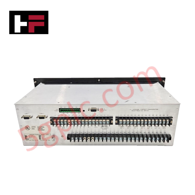
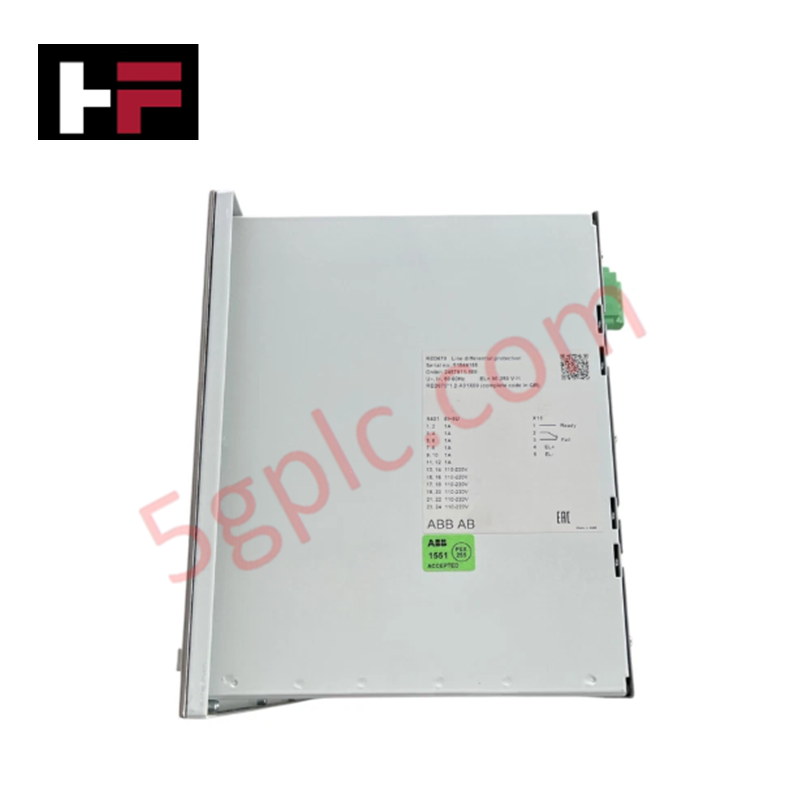
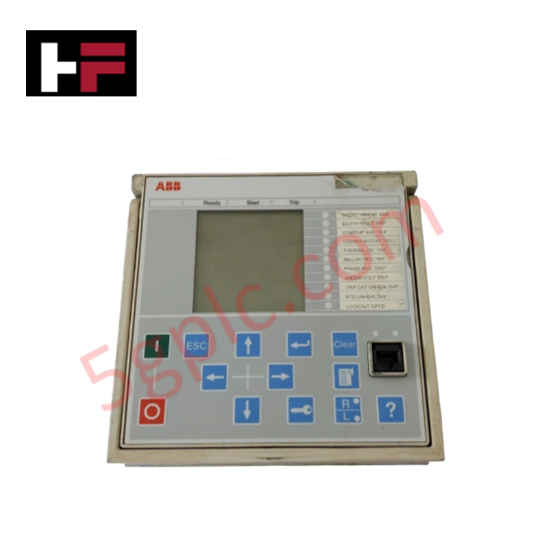
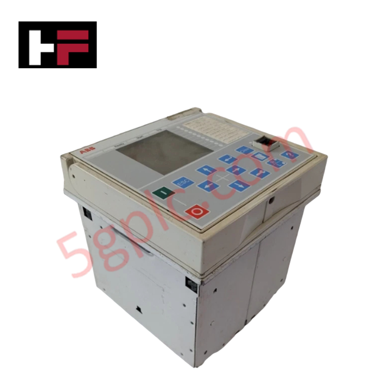
The ABB GPU 2000R 589V2912-50004, also cataloged as the GPU 2000R Generator Protection System, operates as a dedicated hardware component for multi-function phase and ground electrical fault detection within industrial control equipment networks. The unit processes primary current transformer inputs to initiate high-speed protective tripping sequences when measured boundaries are violated.
Hardware Specifications
| Parameter | Specification |
|---|---|
| Model | GPU 2000R 589V2912-50004 |
| Brand | ABB |
| Base Model | GPU 2000R |
| Origin | ABB Standard Supply |
| Phase Current Range | 2.0 - 8.0 A |
| Ground Fault Range | 2.0 - 8.0 A |
| Control Voltage | 38 - 58 VDC |
| System Frequency | 60 Hz |
| Weight | 23.00 lbs |
| Dimensions | Standard rack/panel mounting footprint |
| Operating Temp | Standard industrial operating limits |
| Power Consumption | Dependent on active relay outputs and signal loading |
Profinet / EtherNet/IP Deterministic Networks Performance
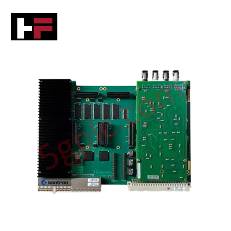
To execute protective functions within sub-cycle intervals, the sampling register configuration maps telemetry data directly to internal execution blocks. The hardware integrates specific sub-assembly profiles to match backplane bus communication velocity metrics found in legacy utility protection integration frameworks. System configuration utilizes rigid I/O density scaling profiles, which depend upon strict firmware flash compatibility parameters between the primary sensor logic and the output contact matrices to suppress jitter during high-current phase shifts over deterministic bus pathways.
Frequently Asked Questions
Q: Does the GPU 2000R chassis assembly support live hot-swap replacement procedures?
A: No. Hot-swapping this protection system is prohibited. All primary secondary current transformer lines must be short-circuited and the 38-58 VDC auxiliary power isolated before physical extraction to avoid inductive breakdown or terminal arcing.
Q: What are the distinct boundary settings for the current inputs on this relay?
A: The physical input circuitry supports an adjustable range from 2.0 A to 8.0 A for both phase and ground current measuring paths, mapped via hardware terminal links.
Q: What actions are required if a firmware flash mismatch is present across the system interface?
A: A firmware variance will disable communication across the internal bus, forcing the unit into an unmapped fault state and blocking the execution of scheduled protection logic.
Field Installation Guidelines
- Chassis Grounding and Bond Verification: Attach a low-impedance copper ground strap directly from the panel frame to the primary copper ground bus bar. Scrape away any paint or non-conductive coatings to ensure zero-potential metal contact.
- Current Transformer Termination Security: Confirm that all terminal screws on the CT measurement blocks are tightened to the factory-specified torque. Open-circuit conditions on live CT secondary lines generate high voltages capable of breaking down internal insulation.
- Control and Signal Wire Segregation: Route the low-voltage 38-58 VDC power lines and communication cables through dedicated, isolated wireways distinct from heavy alternating current phase cables to prevent inductive noise injection.
Additional Information
- 100% Genuine Parts: All products are original and authentic, ensuring reliable industrial performance.
- 30-Day Refund Guarantee: Return any in-stock item within 30 days in original, unopened packaging for a full refund (excluding shipping and fees).
- 12-Month Warranty: Covers defects in materials or workmanship; excludes misuse, normal wear, or unauthorized modifications.
- Worldwide Shipping: We ship via USPS, UPS, FedEx, and DHL. Delivery times vary by country and may be subject to customs or import fees.
- Support & Contact: Technical and warranty assistance is available anytime. Contact us here: Contact.
- Purchase Guidance: Check product specifications and compatibility carefully before ordering to ensure proper application.


Tech & Buying Guide

PLC vs. PC: Navigating the Architectural Differences in Industrial Automation
In the realm of factory automation, professionals often debate the roles of Programmable Logic Controllers (PLCs) and Personal Computers (PCs). While both devices share fundamental computing architectures—including a processor, memory, and an operating system—their design philosophies diverge significantly. Understanding these distinctions is critical for selecting the right hardware for your industrial control systems.

Essential SCADA Features for Modern IoT-Enabled Industrial Automation
The convergence of traditional SCADA systems with the Industrial Internet of Things (IIoT) has redefined factory automation. Choosing a robust platform requires more than just standard monitoring capabilities. In this era of Industry 4.0, your supervisory system must bridge the gap between legacy control systems and enterprise-level data integration.
Selecting Rockwell Automation Allen-Bradley PLCs for Small and Mid-Sized Applications
Rockwell Automation remains a cornerstone in global industrial automation. Their Allen-Bradley brand provides a comprehensive portfolio of control systems designed to meet diverse production requirements. Choosing the right programmable logic controller (PLC) is critical for system reliability and scalability. This guide analyzes the Micro and Compact Logix families to help you select the optimal solution for small and medium-scale projects.