










Product Details
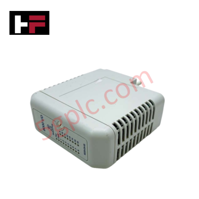
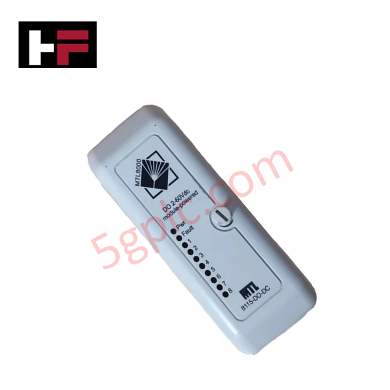
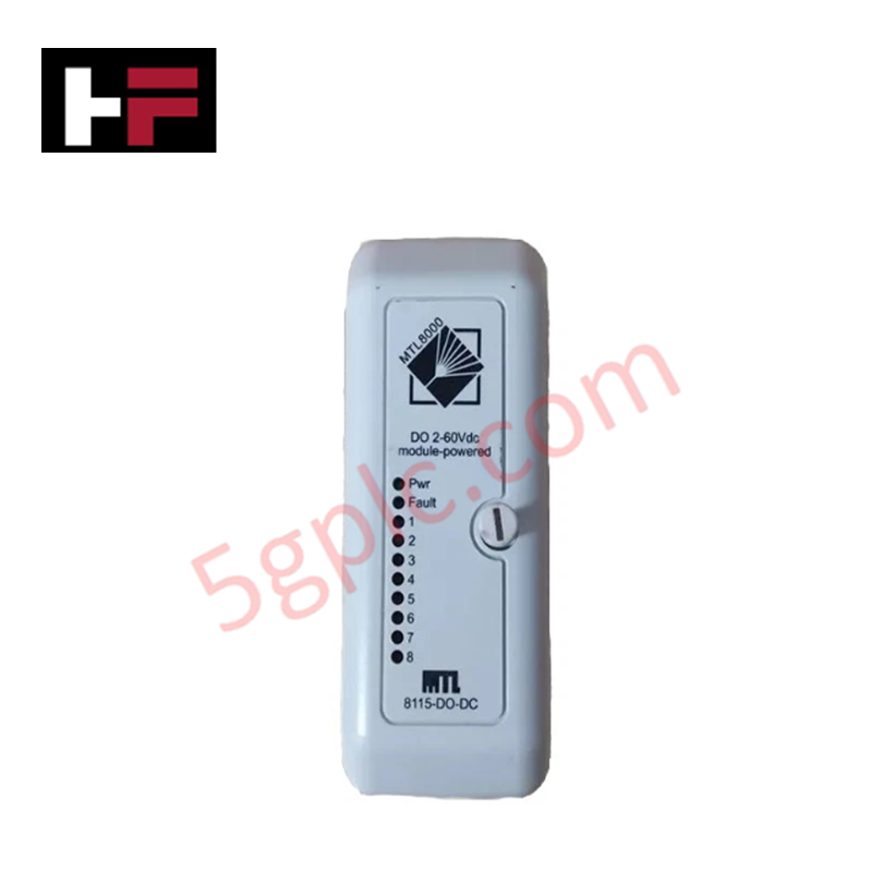
Configured for discrete output signal conditioning and load switching in Emerson process control platforms, the Emerson 8115-DO-DC (8115-DO-DC Discrete Output Module) provides direct physical/electrical execution. It switches 2-60 VDC non-isolated load loops across 8 independent channels based on Railbus command signals.
Hardware Specifications
| Parameter | Specification |
|---|---|
| Model | 8115-DO-DC |
| Brand | Emerson |
| Product Type | Discrete Output Modules |
| Number of Channels | 8 Channels |
| Output Voltage Range | 2-60 VDC (Module Powered, Non-Isolated) |
| Continuous Switched Current | 1 A per channel |
| Peak Switched Current | 4 A (less than 100 ms), 6 A (less than 20 ms) |
| ON Voltage Drop | 0.25 V max |
| OFF Leakage Current | 1.0 mA max |
| Output Modes | Discrete, Momentary or Continuous Pulse |
| Pulse Width Range | 2 ms to 130 s |
| Response Time | 1 ms max (Railbus command to output change) |
| Power Consumption | 70 mA max (45 mA typ) at 12 VDC Railbus |
| Bussed Field Power | 2 to 60 VDC |
| Module Key Code | B6 |
| Module Width | 42 mm |
| Weight | 0.21 kg (0.21 kg net / 1.0 kg shipping) |
| Origin | USA |
| Operating Temp | -20 to 70 deg C |
4-20 mA HART Loop Protocol and Channel Isolation
The 8115-DO-DC operates on a shared bussed field power topology within the Emerson I/O node structure. While discrete outputs handle DC switching currents up to 1 A continuous per channel, internal shielding protects adjacent high-density 4-20 mA HART loop protocol signal paths on the common backplane from capacitive and inductive switching noise. Galvanic isolation between the internal 12 VDC Railbus logic circuit and the 2-60 VDC field power bus ensures backplane communication integrity during heavy load transients.
Frequently Asked Questions
Q: What is the maximum command-to-output latency for the 8115-DO-DC module?
A: The physical response time from receipt of a Railbus switching command to output change is 1 ms maximum.
Q: How does the 8115-DO-DC react if communications with the node processor fail?
A: The module transitions to a designated fail-safe state, holding either a predefined default state or retaining the last valid command value depending on configuration settings.
Q: Can the 8115-DO-DC handle inductive inrush currents from DC relay coils?
A: Yes. Each channel supports peak surge currents up to 4 A for durations under 100 ms, and up to 6 A for brief transients under 20 ms.
Field Installation Guidelines
- Mount the 42 mm module onto the compatible node carrier slot, ensuring the B6 mechanical key alignment matches the carrier base to prevent mis-insertion.
- Connect bussed field power lines within the 2-60 VDC operating window to supply external load loops.
- Terminate field load conductors securely to the module terminal block, ensuring current demands do not exceed 1 A continuous per channel.
- Verify that signal wiring shielding is tied directly to the cabinet functional earth bus bar to mitigate transient electrical noise.
- Maintain adequate ventilation spacing around the carrier assembly to dissipate thermal losses during high-density multi-channel current switching.
Additional Information
- 100% Genuine Parts: All products are original and authentic, ensuring reliable industrial performance.
- 30-Day Refund Guarantee: Return any in-stock item within 30 days in original, unopened packaging for a full refund (excluding shipping and fees).
- 12-Month Warranty: Covers defects in materials or workmanship; excludes misuse, normal wear, or unauthorized modifications.
- Worldwide Shipping: We ship via USPS, UPS, FedEx, and DHL. Delivery times vary by country and may be subject to customs or import fees.
- Support & Contact: Technical and warranty assistance is available anytime. Contact us here: Contact.
- Purchase Guidance: Check product specifications and compatibility carefully before ordering to ensure proper application.




Tech & Buying Guide

Redefining Control Systems: The Rise of Flexible I/O Modules in Industrial Automation
Conventional input-output architectures often limit engineering agility and inflate long-term inventory costs. Today, Flexible Input/Output Modules (FIOM) are transforming how control system engineers design, commission, and maintain automation infrastructure. By allowing individual channel software configuration, FIOM technology bridges the gap between rigid hardware design and dynamic plant requirements.
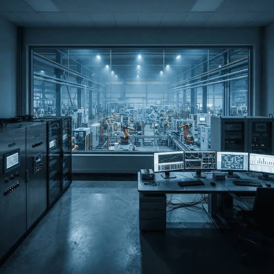
Understanding Modern SCADA Systems: Architecture, Communication Topologies, and Industrial Applications
Supervisory Control and Data Acquisition (SCADA) systems form the digital backbone of modern industrial automation. They collect critical field data, transmit signals across vast distances, and empower plant operators with real-time process visibility. Across modern infrastructures, SCADA solutions streamline centralized control and maintain continuous operational uptime.
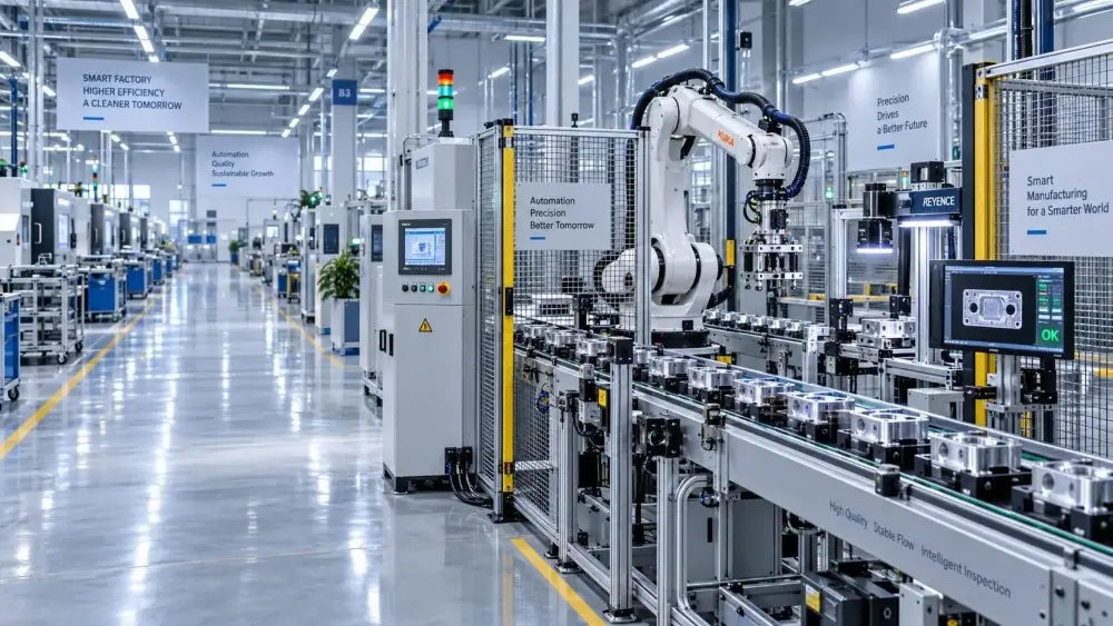
Understanding OPC Servers in Modern Industrial Automation: Principles, Architecture, and Applications
In industrial automation, connecting physical hardware with high-level software remains a primary operational challenge. Factories utilize programmable logic controllers (PLCs), distributed control systems (DCS), human-machine interfaces (HMIs), and smart sensors from diverse vendors. These devices often speak different proprietary protocols. Open Platform Communications (OPC) servers solve this interoperability challenge by standardizing how data flows across factory networks.