


Product Details
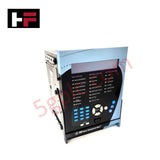
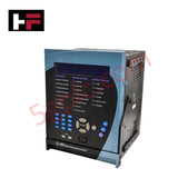
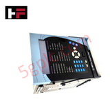
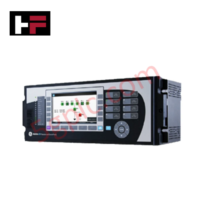
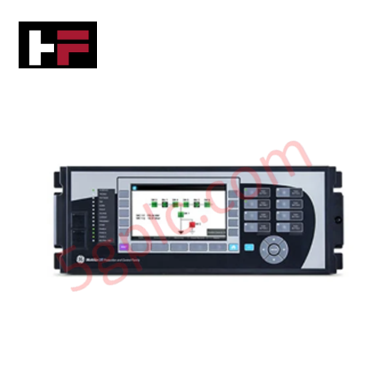
The GE 469-P1-HI-A20-E-H, also cataloged as the 469 Motor Management Relay, operates as a dedicated hardware component for protection, control, and diagnostic tracking within electrical substation and motor control center networks. The device reads current, voltage, and thermal inputs to execute protection logic, managing electrical distribution through isolated digital inputs and analog outputs. Hardware features include an enhanced 40-character LCD interface and conformal coating for industrial environmental resilience.
Hardware Specifications
| Parameter | Specification |
|---|---|
| Model | 469-P1-HI-A20-E-H |
| Brand | GE Multilin |
| Origin | Technical specifications determine final factory origin |
| Weight | Physical enclosure mass varies by mounting configuration |
| Dimensions | Standard 469 series panel cutout dimensions apply |
| Operating Temp | -40 to +60 deg C |
| Power Consumption | Control supply dependent |
| Control Power | 90-300 VDC or 70-265 VAC |
| Line Frequency | 48-62 Hz |
| Digital Inputs | 9 opto-isolated digital inputs |
| Analog Outputs | 4 selectable outputs (0-1 mA or 4-20 mA configurations) |
| Display Type | Enhanced LCD (40 characters) |
| Environmental Protection | Conformal coating for harsh environments |
| Storage Temp | -40 to +80 deg C |
Firmware Flash Compatibility and Deterministic Signal Processing
The internal microprocessor architecture maintains synchronous code execution, utilizing specialized memory blocks to guarantee firmware flash compatibility across standard motor protection configurations. Input monitoring runs on a strict internal clock to provide deterministic measurement tracking of thermal and electrical variables. The I/O backplane processing loops prevent runtime jitter during concurrent tracking of the 9 opto-isolated digital inputs and active analog output matrices.
Frequently Asked Questions
Q: Can the internal I/O modules or display board be extracted while the control power is applied?
A: No. The internal logic circuitry and backplane power traces do not support live hot-swapping. Control power (90-300 VDC or 70-265 VAC) must be completely isolated before servicing internal hardware components to avoid permanent electrical damage or erratic contact states.
Q: How do the opto-isolated digital inputs handle external electrical noise?
A: The 9 digital inputs are equipped with galvanic optical isolation to separate external field wiring loops from the internal logic processor bus. This design absorbs high-frequency transient spikes and prevents common-mode noise from disrupting internal control execution.
Field Installation Guidelines
- Grounding Requirements: Connect a low-impedance copper conductor from the rear panel chassis grounding terminal directly to the main cubicle ground bus to establish an equipotential reference.
- Shielding Protocol: Terminate the external shielding braid of all 4-20 mA analog output lines at the enclosure side only. Grounding both ends of the shield is prohibited to eliminate potential ground loop currents.
- Cable Separation: Route all high-voltage power wiring (auxiliary supply and contact output circuits) through separate metal conduits away from low-voltage analog and digital signal wiring to reduce inductive coupling.
Additional Information
- 100% Genuine Parts: All products are original and authentic, ensuring reliable industrial performance.
- 30-Day Refund Guarantee: Return any in-stock item within 30 days in original, unopened packaging for a full refund (excluding shipping and fees).
- 12-Month Warranty: Covers defects in materials or workmanship; excludes misuse, normal wear, or unauthorized modifications.
- Worldwide Shipping: We ship via USPS, UPS, FedEx, and DHL. Delivery times vary by country and may be subject to customs or import fees.
- Support & Contact: Technical and warranty assistance is available anytime. Contact us here: Contact.
- Purchase Guidance: Check product specifications and compatibility carefully before ordering to ensure proper application.


Tech & Buying Guide

Essential SCADA Features for Modern IoT-Enabled Industrial Automation
The convergence of traditional SCADA systems with the Industrial Internet of Things (IIoT) has redefined factory automation. Choosing a robust platform requires more than just standard monitoring capabilities. In this era of Industry 4.0, your supervisory system must bridge the gap between legacy control systems and enterprise-level data integration.

Selecting Rockwell Automation Allen-Bradley PLCs for Small and Mid-Sized Applications
Rockwell Automation remains a cornerstone in global industrial automation. Their Allen-Bradley brand provides a comprehensive portfolio of control systems designed to meet diverse production requirements. Choosing the right programmable logic controller (PLC) is critical for system reliability and scalability. This guide analyzes the Micro and Compact Logix families to help you select the optimal solution for small and medium-scale projects.

Strategic Selection: Choosing the Right SCADA Software for Your PLC Project
In industrial automation, the SCADA (Supervisory Control and Data Acquisition) system acts as the bridge between raw machine data and actionable human intelligence. Selecting the incorrect software platform can lead to integration bottlenecks, scalability issues, and excessive long-term maintenance costs. As an automation consultant with 15 years of experience, I have guided many projects through the selection process. Below are the essential criteria for choosing a platform that ensures both performance and longevity.