


Product Details
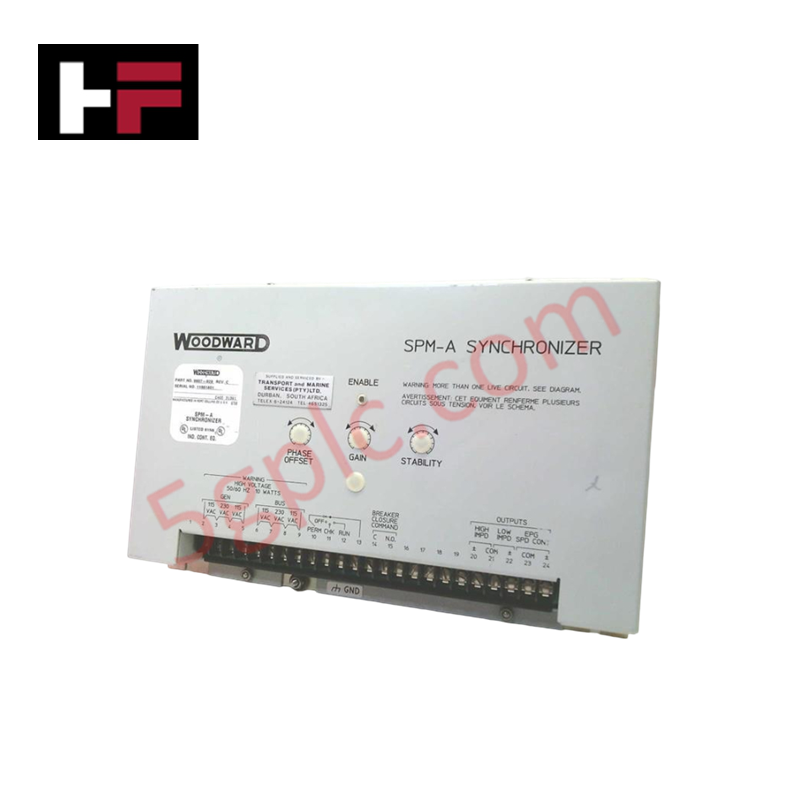
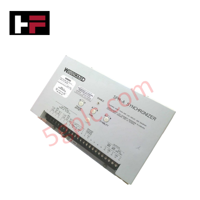
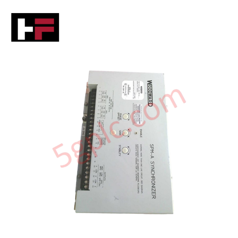
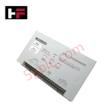
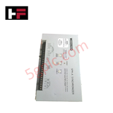
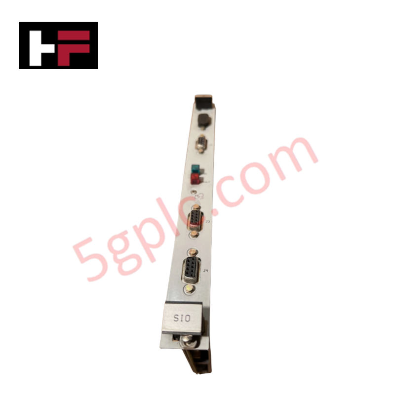
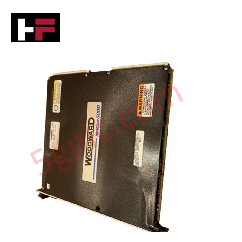
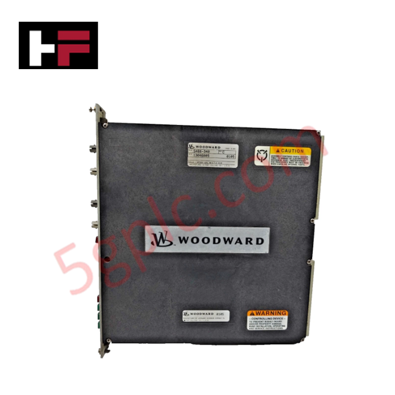
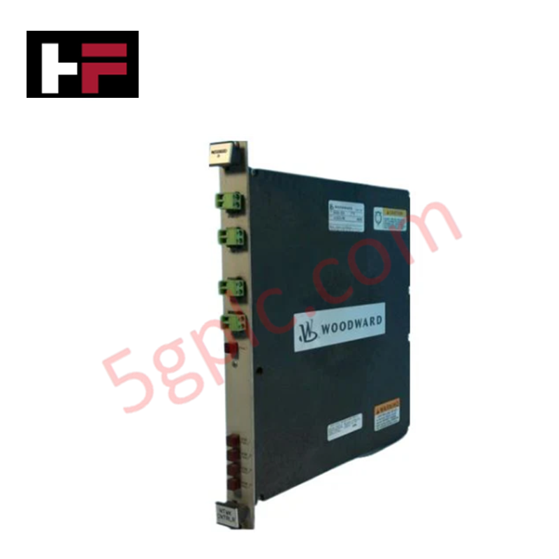
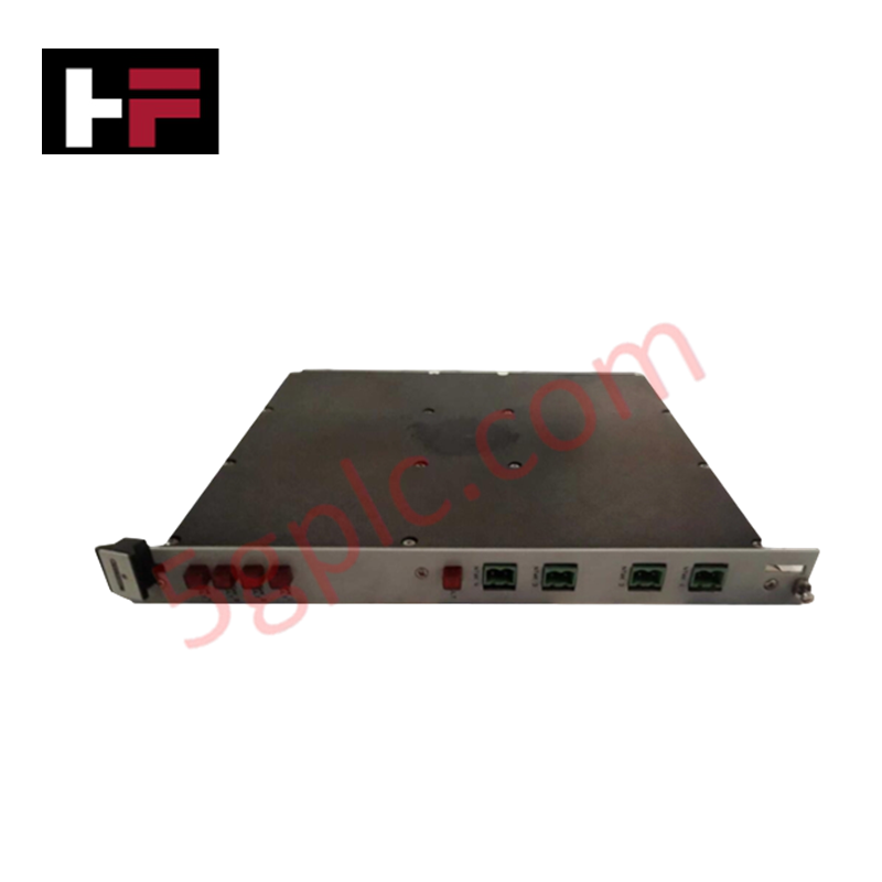
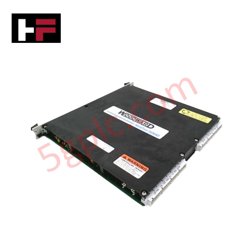
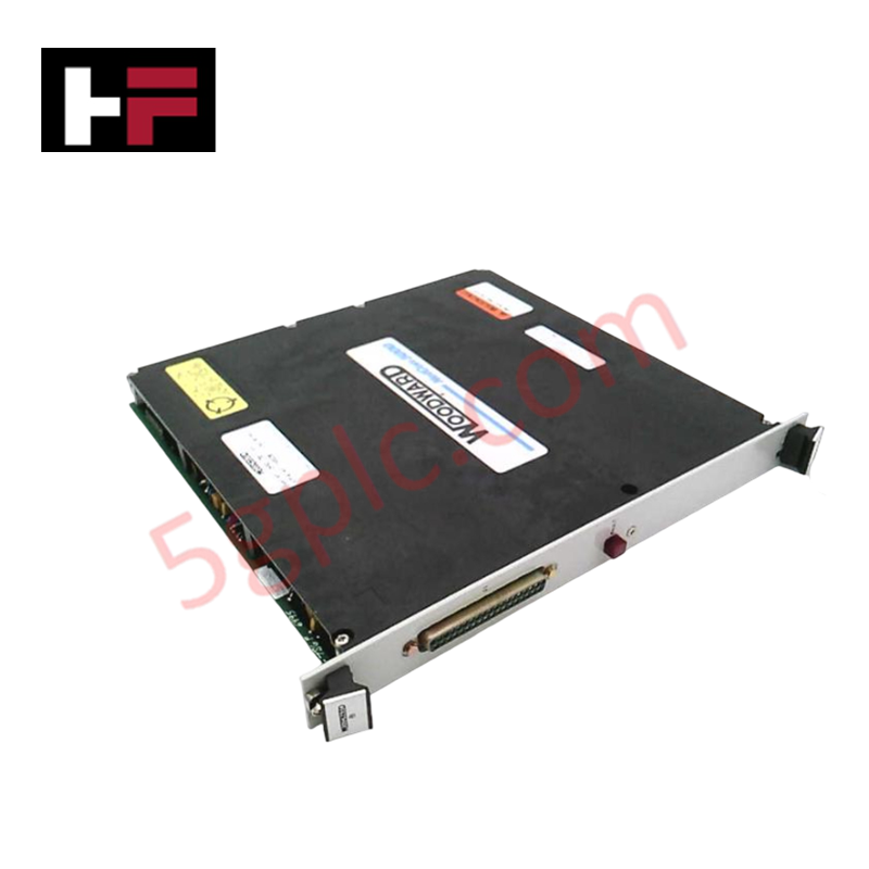
Configured for generator synchronization and phase alignment in parallel power systems, the Woodward 9907-028 (9907-028 Synchronizer) provides direct physical/electrical execution of generator speed matching and breaker closure signaling.
Hardware Specifications
| Parameter | Specification |
|---|---|
| Model | 9907-028 |
| Brand | Woodward |
| Weight | 2.2 kg (5 lbs) |
| Dimensions | Not specified |
| Operating Temp | -45 to 70 deg C |
| Power Consumption | 5 W |
| Voltage Input | 115/230 VAC RMS (+/- 10%) |
| Frequency | 50/60 Hz |
| Phase Angle | +/- 10 deg |
Actuator Loop Feedback Response
The 9907-028 synchronizer modulates prime mover rotational speed to align the generator phase angle within a +/- 10 deg window relative to the bus. To achieve a stable actuator loop feedback response, the device integrates adjustable dynamic settings that allow for precise tuning of the frequency correction output. The controller interfaces with external speed governors, such as the 2301 or EPG series, to influence engine speed without performing voltage matching. The internal logic provides four selectable operational modes—RUN, CHECK, PERMISSIVE, and OFF—which dictate the synchronization behavior and the activation of the circuit breaker closure signals.
Frequently Asked Questions
Q: Does the 9907-028 perform automatic voltage matching during synchronization?
A: No, this model does not feature voltage matching capabilities. It focuses exclusively on phase angle and frequency matching to facilitate parallel operation.
Q: How do the different operational modes (RUN, CHECK, PERMISSIVE) affect synchronization?
A: RUN mode enables full synchronization and breaker closure signals. CHECK mode performs synchronization calculations but inhibits breaker closure. PERMISSIVE mode allows synchronization monitoring but restricts the unit from modifying the engine speed.
Field Installation Guidelines
- Mounting: Install the synchronizer within a switchgear enclosure. Ensure adequate ventilation to maintain operation within the rated -45 to 70 deg C range, though optimal stability is observed between 10 deg C and 30 deg C.
- Wiring: Use shielded cabling for all sensing inputs (bus/generator voltage) and control outputs to prevent electrical noise interference.
- Switch Configuration: Install a user-defined multi-position switch to toggle between the four operational states. Verify the wiring of the switch inputs corresponds to the desired mode definitions (RUN, CHECK, PERMISSIVE, OFF).
- Validation: During initial commissioning, monitor the phase angle error and frequency drift. Adjust internal dynamic settings as necessary to achieve smooth synchronization without excessive speed hunting or oscillation before breaker closure.
Additional Information
- 100% Genuine Parts: All products are original and authentic, ensuring reliable industrial performance.
- 30-Day Refund Guarantee: Return any in-stock item within 30 days in original, unopened packaging for a full refund (excluding shipping and fees).
- 12-Month Warranty: Covers defects in materials or workmanship; excludes misuse, normal wear, or unauthorized modifications.
- Worldwide Shipping: We ship via USPS, UPS, FedEx, and DHL. Delivery times vary by country and may be subject to customs or import fees.
- Support & Contact: Technical and warranty assistance is available anytime. Contact us here: Contact.
- Purchase Guidance: Check product specifications and compatibility carefully before ordering to ensure proper application.


Tech & Buying Guide

Understanding Dry Contacts in PLC Wiring: An Industrial Automation Guide
Mastering contact switching principles is essential for reliable control panels. Field devices and PLCs interface through dry or wet contacts. This technical guide examines the mechanics of dry contacts, explores their wiring architectures, and evaluates their key advantages in industrial automation.

Ultimate Commissioning Checklist for Industrial Automation Systems: An Engineering Guide
Commissioning is the most decisive phase of an industrial automation project, transforming control hardware and software into an operational facility. Thorough testing prevents costly startup delays and builds customer confidence. This guide covers essential checklists, electrical standards, and best practices.

Redundant Automation Systems: Core Architecture, Business Value, and Technical Advantages
Unplanned downtime poses a major financial threat to process manufacturing. To prevent costly interruptions, engineers deploy redundant PLC and DCS architectures that ensure continuous operation when hardware fails. This technical guide explores redundancy principles, critical system nodes, and real-world scenarios.