


Product Details
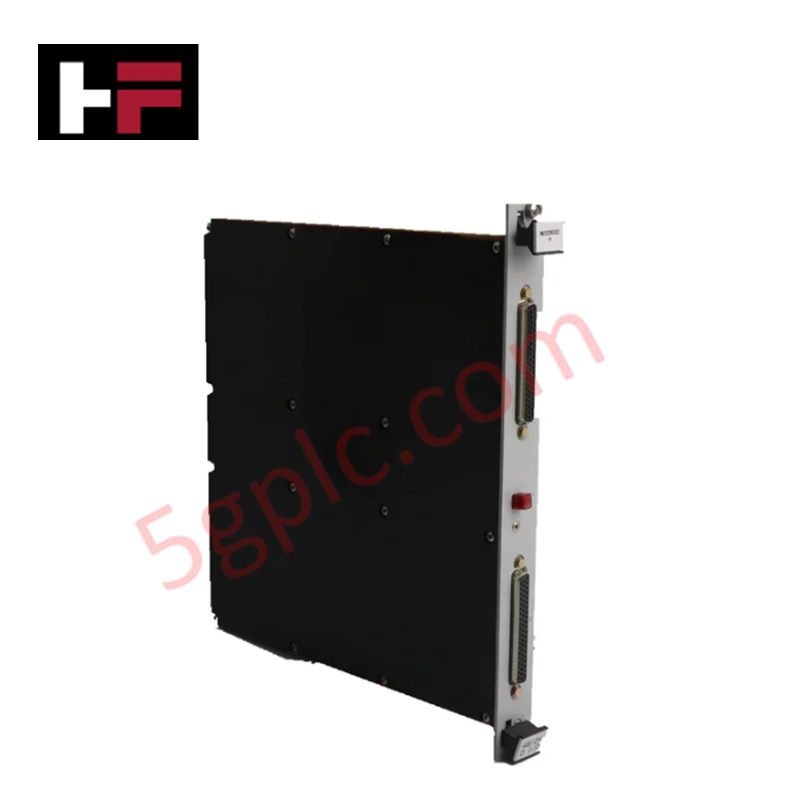
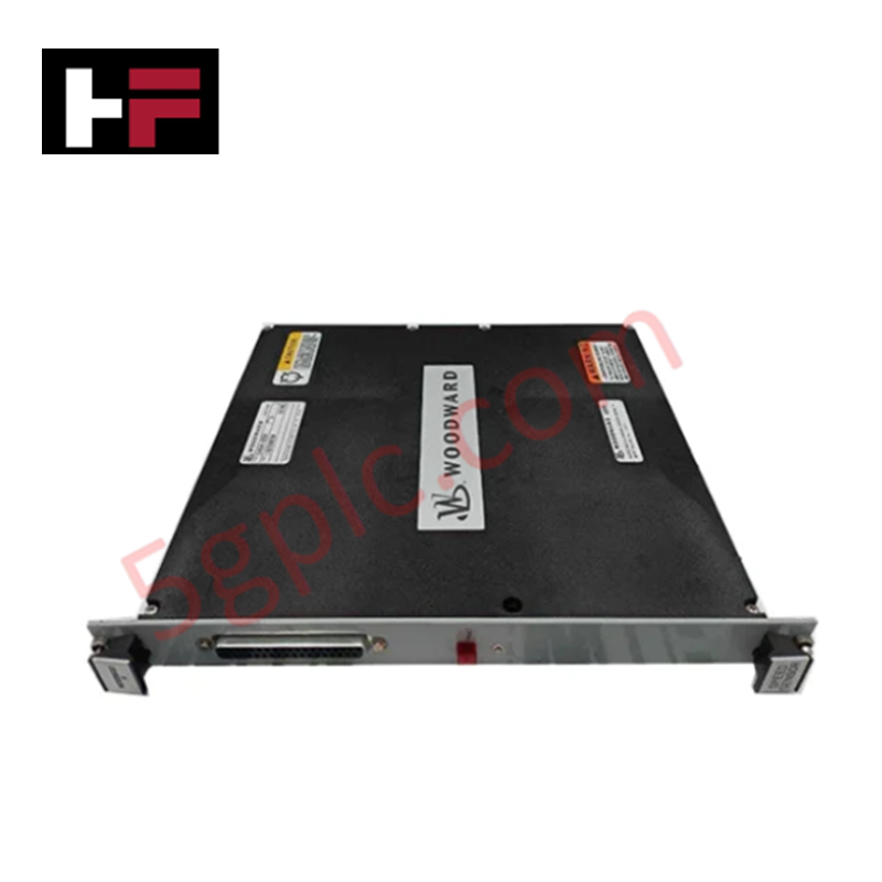
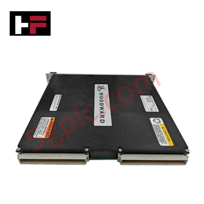
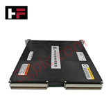
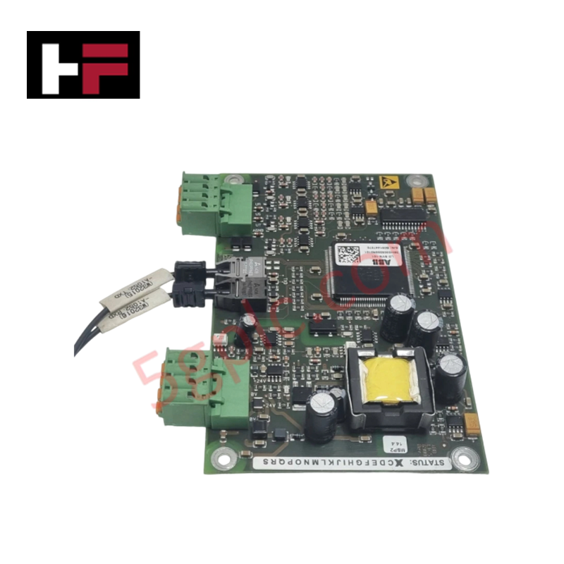
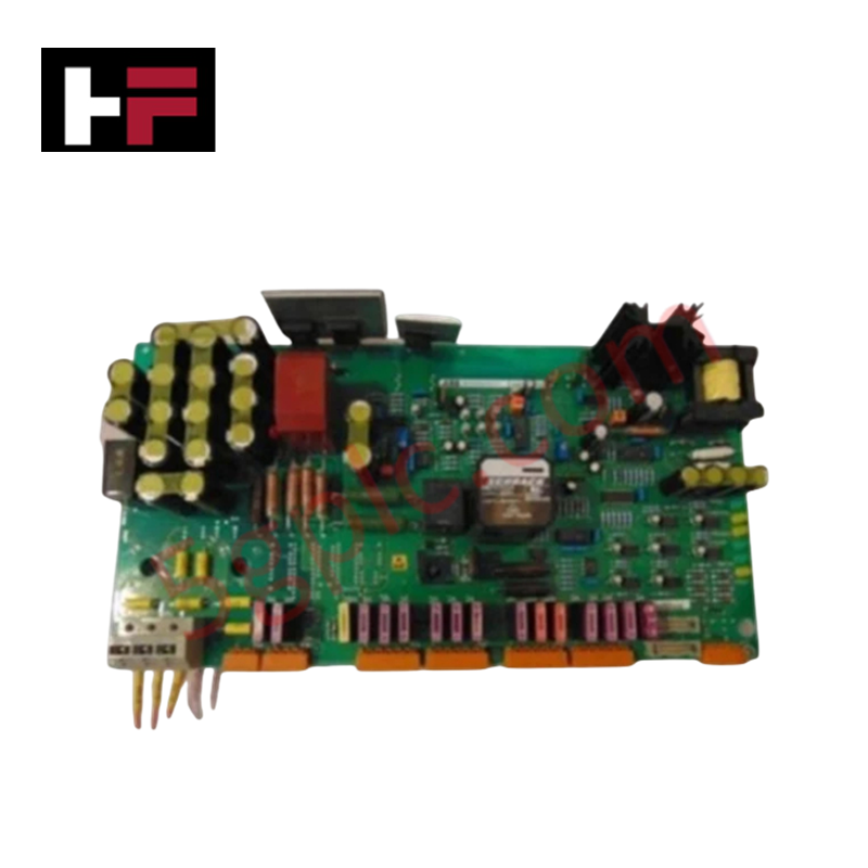
The Woodward 5466-1000, also cataloged as the 5466-1000 Power Supply module, operates as a dedicated hardware component for power distribution within control system backplanes.
Hardware Specifications
| Parameter | Specification |
|---|---|
| Model | 5466-1000 |
| Brand | Woodward |
| Origin | USA |
| Weight | Not specified |
| Dimensions | 2-slot configuration |
| Operating Temp | Not specified |
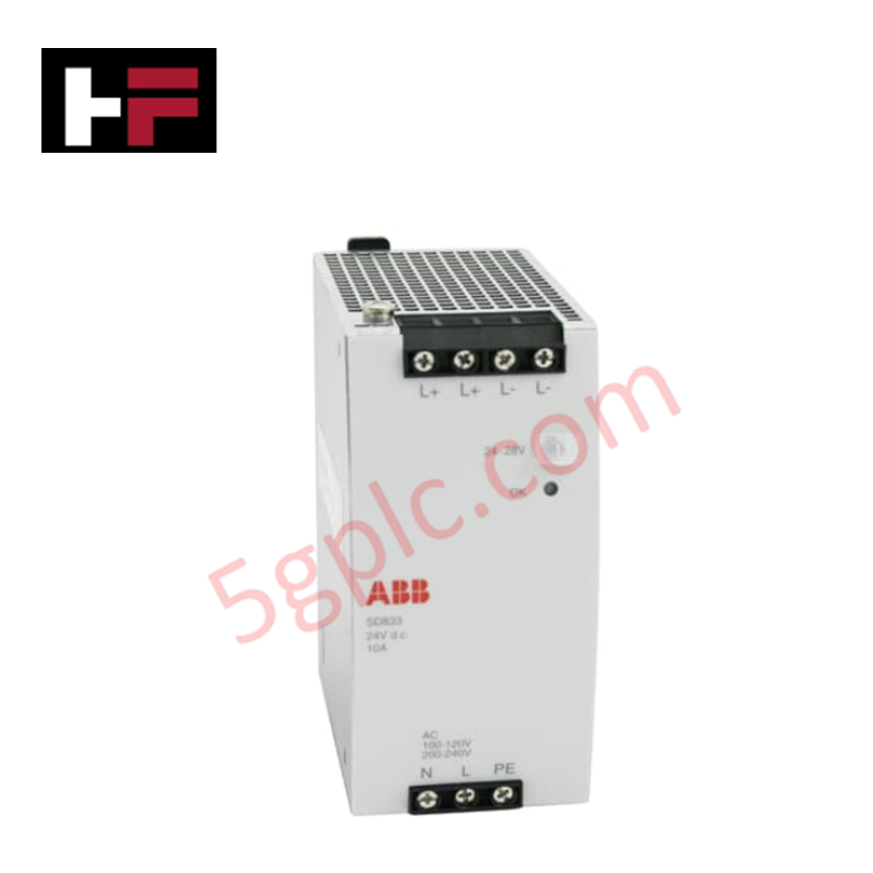
| Power Consumption | 24 VDC input |
| Module Capacity | Up to 2 modules simultaneously |
Thermal Heat Sink Dissipation Profiles
The 5466-1000 utilizes internal heat dissipation architectures designed to manage the thermal loads generated during the conversion and distribution of 24 VDC power. To ensure optimal performance and prevent thermal derating, the module must be installed in an environment that facilitates adequate airflow through the chassis vents. Users should verify that the ambient operating temperature does not exceed the specified thermal ceiling for the specific control cabinet enclosure to prevent degradation of the internal power regulation components.
Frequently Asked Questions
Q: Is the 5466-1000 module capable of hot-swapping under load?
A: Installation or removal of the power supply while the circuit is live is prohibited unless the installation environment is explicitly confirmed as non-hazardous. Always ensure the power source is de-energized prior to insertion or extraction.
Q: What are the primary physical constraints for installing this module?
A: The module requires a 2-slot space within the rack. When installing, ensure all connector pins are parallel and straight before seating the module into the motherboard connectors. Force should be applied via the extraction handle to ensure full engagement.
Field Installation Guidelines
- Verify that the input power supply is de-energized and locked out.
- Inspect the module connector pins for any signs of physical deformation or misalignment; ensure they are perfectly parallel and straight.
- Align the module with the designated 2-slot chassis guide rails.
- Apply consistent pressure to the extraction handle to seat the module, ensuring the module connector pins achieve full contact with the motherboard connectors.
- Secure the module within the rack and perform a voltage check on the output rails before reconnecting field loads.
Additional Information
- 100% Genuine Parts: All products are original and authentic, ensuring reliable industrial performance.
- 30-Day Refund Guarantee: Return any in-stock item within 30 days in original, unopened packaging for a full refund (excluding shipping and fees).
- 12-Month Warranty: Covers defects in materials or workmanship; excludes misuse, normal wear, or unauthorized modifications.
- Worldwide Shipping: We ship via USPS, UPS, FedEx, and DHL. Delivery times vary by country and may be subject to customs or import fees.
- Support & Contact: Technical and warranty assistance is available anytime. Contact us here: Contact.
- Purchase Guidance: Check product specifications and compatibility carefully before ordering to ensure proper application.


Tech & Buying Guide
Mastering Functional Safety Terminology in Industrial Automation
In modern process control and factory automation, managing operational risk is a top engineering priority. High-speed machinery, high-pressure vessels, and continuous processes present constant hazards to personnel and equipment. Modern plant operations rely heavily on functional safety strategies to mitigate these risks. This guide breaks down the essential functional safety terminology that every control systems engineer should master.

Understanding Dry Contacts in PLC Wiring: An Industrial Automation Guide
Mastering contact switching principles is essential for reliable control panels. Field devices and PLCs interface through dry or wet contacts. This technical guide examines the mechanics of dry contacts, explores their wiring architectures, and evaluates their key advantages in industrial automation.

Ultimate Commissioning Checklist for Industrial Automation Systems: An Engineering Guide
Commissioning is the most decisive phase of an industrial automation project, transforming control hardware and software into an operational facility. Thorough testing prevents costly startup delays and builds customer confidence. This guide covers essential checklists, electrical standards, and best practices.