










Product Details
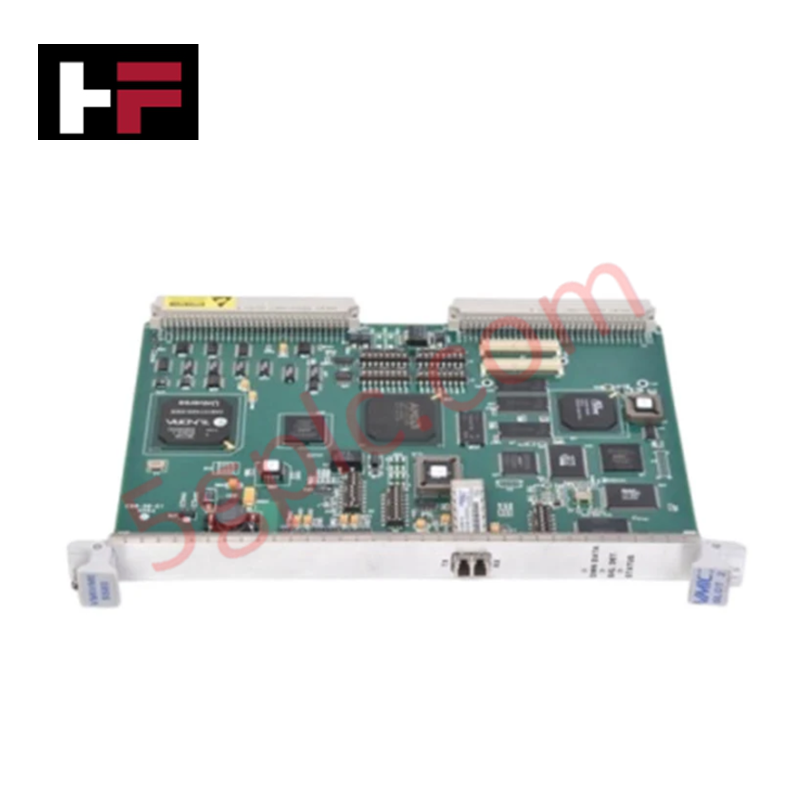
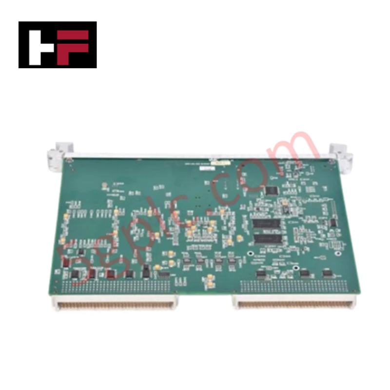
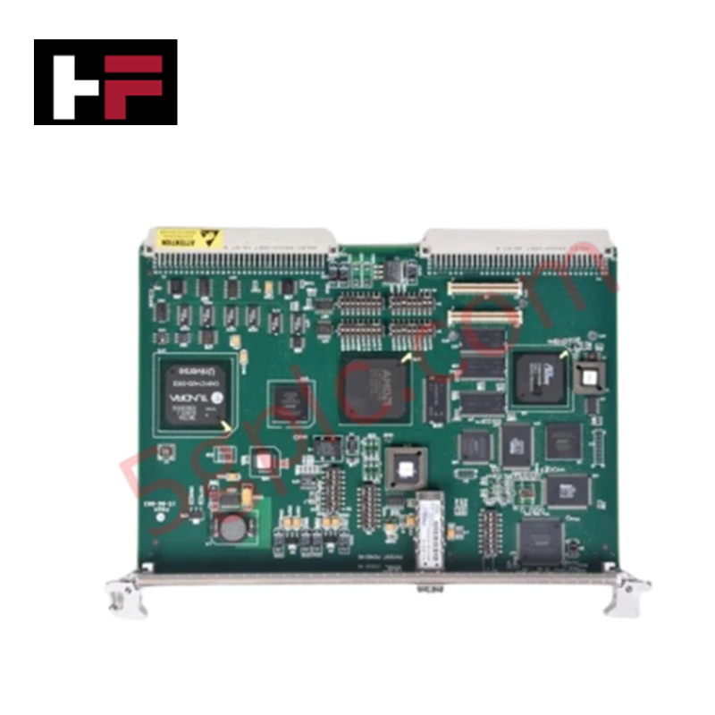
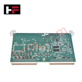
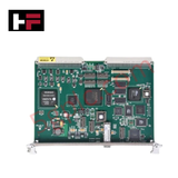
The GE VMIVME5565 332-015565-010 serves as the primary VMIVME5565 Reflective Memory Node Card utilized to execute high-speed deterministic data replication across real-time distributed network platforms.
Hardware Specifications
| Parameter | Specification |
|---|---|
| Model | VMIVME5565 332-015565-010 |
| Brand | GE Fanuc |
| Origin | United States |
| Weight | Standard Module Weight |
| Dimensions | PMC, PCI Express, PCI, or VME Form Factors |
| Operating Temp | 0 - 60 deg C |
| Power Consumption | Slot Interface Dependent |
| Serial Connection Speed | 2.12 Gbaud |
| Dynamic Packet Sizes | 4 to 64 bytes |
| Network Data Rate | Up to 170 Mbyte/s sustained |
| Transfer Latency | 450 to 500 nanoseconds between nodes |
| Onboard Memory | 128 Mbytes or 256 Mbytes SDRAM |
| Multimode Fiber Limit | Up to 300 meters |
| Single Mode Fiber Limit | Up to 10 kilometers |
Profinet / EtherNet/IP Deterministic Networks and Error Management
The network interface achieves low-latency data replication by using a dedicated 2.12 Gbaud fiber optic ring structure separate from standard Profinet / EtherNet/IP deterministic networks. The embedded hardware logic manages error detection automatically to protect against lost data during packet transmission, preventing memory desynchronization across the node grid. This architecture bypasses standard network stack overhead by mapping remote memory configurations directly to the local SDRAM array.
Frequently Asked Questions
Q: What defines the switching delay or synchronization lag between nodes on the reflective memory ring?
A: The physical data transmission latency is constrained to 450 to 500 nanoseconds between consecutive nodes. Total ring latency accumulates based on the total fiber length and the number of active node cards installed in the loop.
Q: How do firmware flash compatibility settings affect node interruption execution?
A: Interruption transfers across nodes require matching board support package drivers and target operating system versions. Incompatible initialization parameters will inhibit node-to-node interrupt propagation, leading to standard register write blocks.
Field Installation Guidelines
- Fiber Optic Bend Radius: Maintain the minimum recommended bend radius for all multimode and single mode fiber connections to prevent attenuation of the 2.12 Gbaud serial laser signal.
- Transceiver Matching Validation: Ensure that the fiber optic transceivers on adjacent node modules correspond exactly in wavelength specifications; do not mix multimode links with single mode runs.
- Static Discharge Prevention: Ground all field tools and wear a calibrated ESD wrist strap before handling the card components to prevent electrostatic degradation of the onboard SDRAM circuits.
Additional Information
- 100% Genuine Parts: All products are original and authentic, ensuring reliable industrial performance.
- 30-Day Refund Guarantee: Return any in-stock item within 30 days in original, unopened packaging for a full refund (excluding shipping and fees).
- 12-Month Warranty: Covers defects in materials or workmanship; excludes misuse, normal wear, or unauthorized modifications.
- Worldwide Shipping: We ship via USPS, UPS, FedEx, and DHL. Delivery times vary by country and may be subject to customs or import fees.
- Support & Contact: Technical and warranty assistance is available anytime. Contact us here: Contact.
- Purchase Guidance: Check product specifications and compatibility carefully before ordering to ensure proper application.


Tech & Buying Guide

Mastering the Siemens PLC Scan Cycle: How the CPU Executes Automation Programs
Industrial automation relies heavily on programmable logic controllers (PLCs) to manage complex manufacturing processes. Many engineers dive straight into programming without mastering the underlying architecture. However, understanding how a PLC CPU executes a program ensures reliable system design. Therefore, mastering the scan cycle optimizes both performance and troubleshooting in modern control systems.

How to Connect to Siemens S7 PLCs: 5 Essential Communication Methods
Establishing a reliable hardware link between a programming terminal and a Siemens SIMATIC controller is essential for engineering workflows. Field engineers rely on distinct physical layers, ranging from legacy serial connections to high-speed Industrial Ethernet protocols. Modern factory automation environments prioritize fast data transfer and seamless driver integration. Selecting the correct connection method simplifies program downloads, online monitoring, and system troubleshooting in complex control systems.

Will PLCs Become Obsolete? The Future of Control Systems in Industry 4.0
Modern manufacturing is undergoing a rapid technological transformation driven by Industry 4.0 innovations. Technologies like Artificial Intelligence (AI), Machine Learning (ML), and the Industrial Internet of Things (IIoT) are dominating discussions across the factory automation sector. Consequently, many engineers wonder if these advanced digital tools will eventually replace traditional Programmable Logic Controllers (PLCs). However, evaluating the core physics of industrial operations reveals a very different reality for control systems.