


Product Details
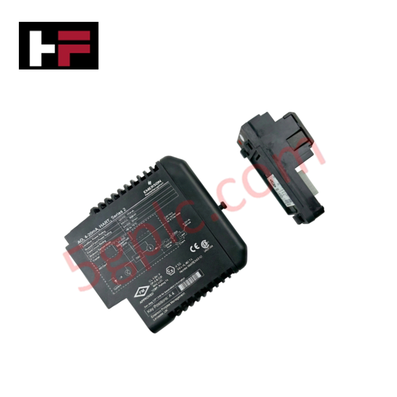
The Emerson VE4015, also cataloged as the VE4015 I/O Module, operates as a dedicated hardware component for multi-function signal processing within DeltaV control platforms. Configured for high-density I/O integration, this module provides direct physical interface capability to support complex control loop execution through an integrated 32-channel terminal block architecture.
Hardware Specifications
| Parameter | Specification |
|---|---|
| Model | VE4015 |
| Brand | Emerson |
| Origin | N/A |
| Weight | 0.65 kg (1.43 lbs) |
| Dimensions | Standard DeltaV S-Series Form Factor |
| Operating Temp | Standard Industrial Ambient |
| Power Consumption | 24 VDC Logic Level |
| Channel Count | 32 Channels |
Channel-to-Channel Isolation and Connectivity
The VE4015 architecture utilizes channel-to-channel isolation to prevent potential electrical propagation between discrete or analog loop segments. This isolation ensures that faults in individual field circuits remain localized, preventing cross-channel interference and protecting backplane-level logic. The module supports 24 VDC logic thresholds, maintaining compatibility with standard field-side sensing and actuation hardware while ensuring high signal integrity across the internal bus communication.
Frequently Asked Questions
Q: Does the VE4015 support hot-swapping while the backplane is energized?
A: The VE4015 is designed for hot-swap capability. Ensure that the module is properly seated in the assigned slot before establishing the latching mechanism to prevent intermittent contact on the I/O bus during operation.
Q: How should unused channels on the terminal block be configured?
A: Unused channels should be left disconnected. Ensure that no stray field wiring is left in proximity to active terminals to avoid induced noise or accidental short-circuiting to the common rail.
Field Installation Guidelines
- Mounting: Secure the module onto the designated DeltaV I/O carrier. Ensure the mechanical guide pins are properly aligned with the backplane connector to avoid pin damage during insertion.
- Grounding: Terminate shielded field wiring at the integrated grounding bar on the terminal block. Maintain a low-impedance path to the cabinet earth bus to minimize electromagnetic interference (EMI) susceptibility.
- Wiring: Route field signal conductors through non-metallic wire ducts or grounded metal conduits separated from high-voltage AC lines. Strip conductors to the specified length to ensure full engagement within the terminal block clamping mechanism.
- Verification: Conduct a point-to-point loop test after installation to verify channel mapping and input/output signal logic before commissioning the associated control software.
Additional Information
- 100% Genuine Parts: All products are original and authentic, ensuring reliable industrial performance.
- 30-Day Refund Guarantee: Return any in-stock item within 30 days in original, unopened packaging for a full refund (excluding shipping and fees).
- 12-Month Warranty: Covers defects in materials or workmanship; excludes misuse, normal wear, or unauthorized modifications.
- Worldwide Shipping: We ship via USPS, UPS, FedEx, and DHL. Delivery times vary by country and may be subject to customs or import fees.
- Support & Contact: Technical and warranty assistance is available anytime. Contact us here: Contact.
- Purchase Guidance: Check product specifications and compatibility carefully before ordering to ensure proper application.


Tech & Buying Guide

Essential Motion Control Commands: A Practical Guide for Engineers
Automation engineers often rely on precise position and speed control to drive modern factory machinery. Modern industrial systems, such as Programmable Logic Controllers (PLCs) and Distributed Control Systems (DCS), depend heavily on standardized motion instructions. Mastering these commands ensures operational safety, protects mechanical components, and optimizes cycle times across production lines.

The Role of Intrinsic Safety Barriers in PLC and DCS Architectures
Implementing robust protection in hazardous industrial environments represents a fundamental safety requirement in factory automation. Process facilities often handle volatile gases, dusts, and chemical agents that pose significant combustion risks. Consequently, control system engineers must deploy energy-limiting interfaces to isolate safe-area control cabinets from hazardous-area field instrumentation. This article examines the function, selection, and electrical principles of intrinsic safety barriers within modern PLC and DCS networks.

Architectural Selection and Scale Classification of PLC Systems in Industrial Automation
Selecting the correct control platform represents a foundational engineering decision in factory automation. System designers must carefully balance technical parameters against long-term operational requirements when implementing a Programmable Logic Controller (PLC). This article examines the critical evaluation metrics, physical scale classifications, and operational architectures of modern control systems.