


Product Details
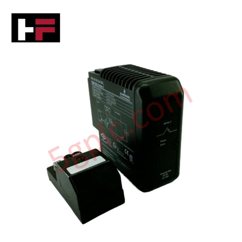
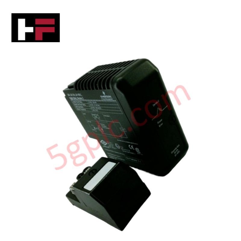
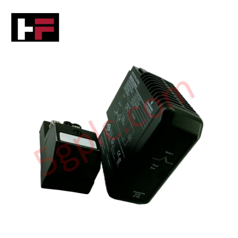
Configured for analog signal acquisition in DeltaV I/O subsystems, the Emerson VE4003S2B3 (VE4003S2B3 Analog Input Termination Block) provides direct physical/electrical execution of 8-channel 4-20 mA signal interfacing.
Hardware Specifications
| Parameter | Specification |
| Model | VE4003S2B3 |
| Brand | Emerson |
| Origin | USA |
| Weight | Not specified |
| Dimensions | Standard M-series terminal block footprint |
| Operating Temp | Not specified |
| Power Consumption | Passive signal distribution |
| Channel Count | 8 channels |
| Signal Input | 4-20 mA (4-wire compatible) |
Process Control: Channel-to-Channel Isolation
The VE4003S2B3 termination block is engineered to maintain signal integrity through systematic channel-to-channel isolation on the DeltaV I/O carrier. This physical architecture ensures that high-voltage transients or field-side faults in one channel do not propagate across the common terminal block assembly, protecting both the I/O card and the controller backplane. The block accommodates 24 VDC field power distribution, with internal routing paths optimized to minimize impedance while maintaining strict dielectric separation between discrete or analog signal paths.
Frequently Asked Questions (FAQ)
Q: Does this termination block support 2-wire transmitter configurations?
A: The VE4003S2B3 is specifically designed for 4-wire analog input applications where the transmitter is powered by an external source. Attempting to use this block for 2-wire loop-powered transmitters may result in signal errors or lack of loop power.
Q: Is this module compatible with all M-series analog input cards?
A: The VE4003S2B3 is designed for use with compatible M-series analog input cards. Ensure that the I/O card configuration and the specific card hardware support the 4-wire, 8-channel input interface before installation.
Field Installation Guidelines
-
Mounting: Seat the terminal block onto the M-series I/O carrier. Verify that the mechanical keying pins are aligned with the corresponding I/O card slot to prevent improper mating and potential electrical shorts.
-
Wiring: Terminate field wiring according to the loop diagram for 4-wire transmitters. Use shielded twisted pair cabling to maintain signal noise immunity. Ensure that shields are tied to the designated cabinet grounding lug on the carrier to prevent ground loops.
-
Torque: Tighten terminal screws to the manufacturer-specified torque to ensure low-resistance contact and prevent wire pull-out under vibration.
-
Verification: Verify that the field power voltage at the transmitter matches the 24 VDC requirements before establishing loop continuity. Ensure no foreign voltage is present on the signal lines.
Additional Information
- 100% Genuine Parts: All products are original and authentic, ensuring reliable industrial performance.
- 30-Day Refund Guarantee: Return any in-stock item within 30 days in original, unopened packaging for a full refund (excluding shipping and fees).
- 12-Month Warranty: Covers defects in materials or workmanship; excludes misuse, normal wear, or unauthorized modifications.
- Worldwide Shipping: We ship via USPS, UPS, FedEx, and DHL. Delivery times vary by country and may be subject to customs or import fees.
- Support & Contact: Technical and warranty assistance is available anytime. Contact us here: Contact.
- Purchase Guidance: Check product specifications and compatibility carefully before ordering to ensure proper application.


Tech & Buying Guide

Essential Motion Control Commands: A Practical Guide for Engineers
Automation engineers often rely on precise position and speed control to drive modern factory machinery. Modern industrial systems, such as Programmable Logic Controllers (PLCs) and Distributed Control Systems (DCS), depend heavily on standardized motion instructions. Mastering these commands ensures operational safety, protects mechanical components, and optimizes cycle times across production lines.

The Role of Intrinsic Safety Barriers in PLC and DCS Architectures
Implementing robust protection in hazardous industrial environments represents a fundamental safety requirement in factory automation. Process facilities often handle volatile gases, dusts, and chemical agents that pose significant combustion risks. Consequently, control system engineers must deploy energy-limiting interfaces to isolate safe-area control cabinets from hazardous-area field instrumentation. This article examines the function, selection, and electrical principles of intrinsic safety barriers within modern PLC and DCS networks.

Architectural Selection and Scale Classification of PLC Systems in Industrial Automation
Selecting the correct control platform represents a foundational engineering decision in factory automation. System designers must carefully balance technical parameters against long-term operational requirements when implementing a Programmable Logic Controller (PLC). This article examines the critical evaluation metrics, physical scale classifications, and operational architectures of modern control systems.