










Product Details
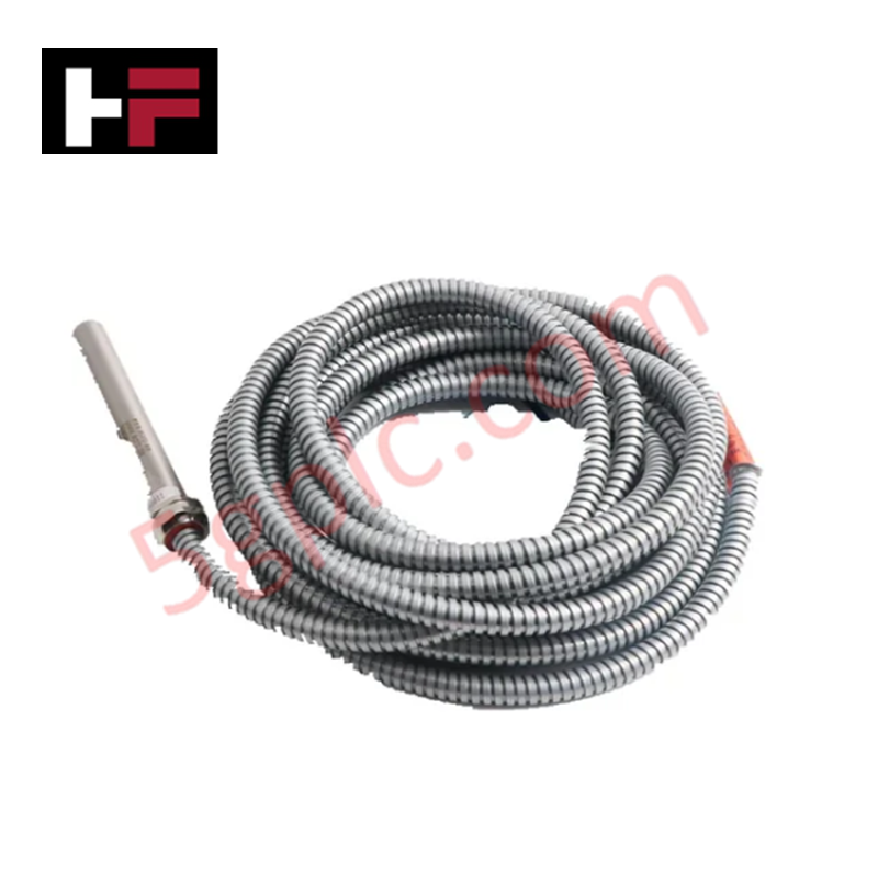
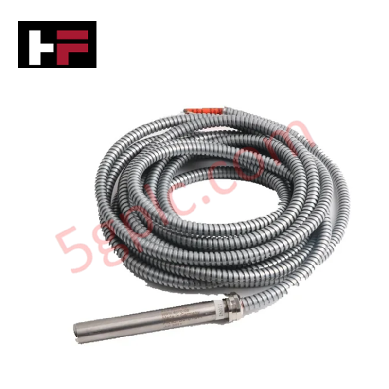
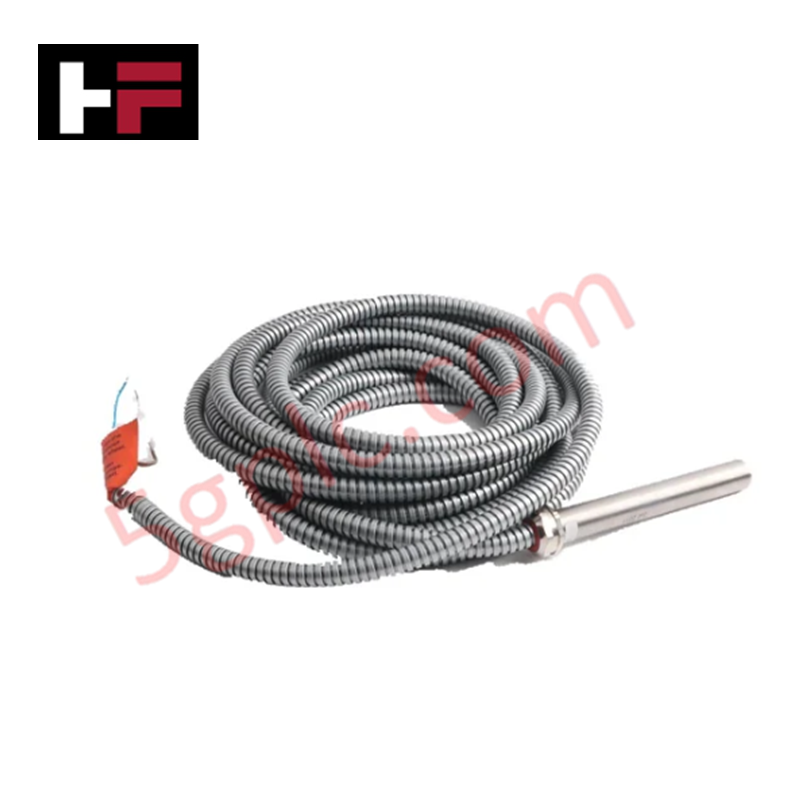
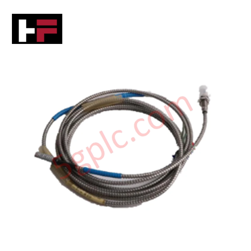
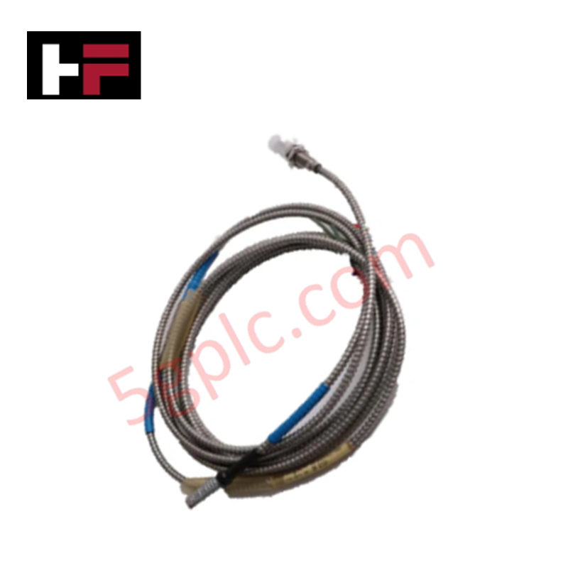
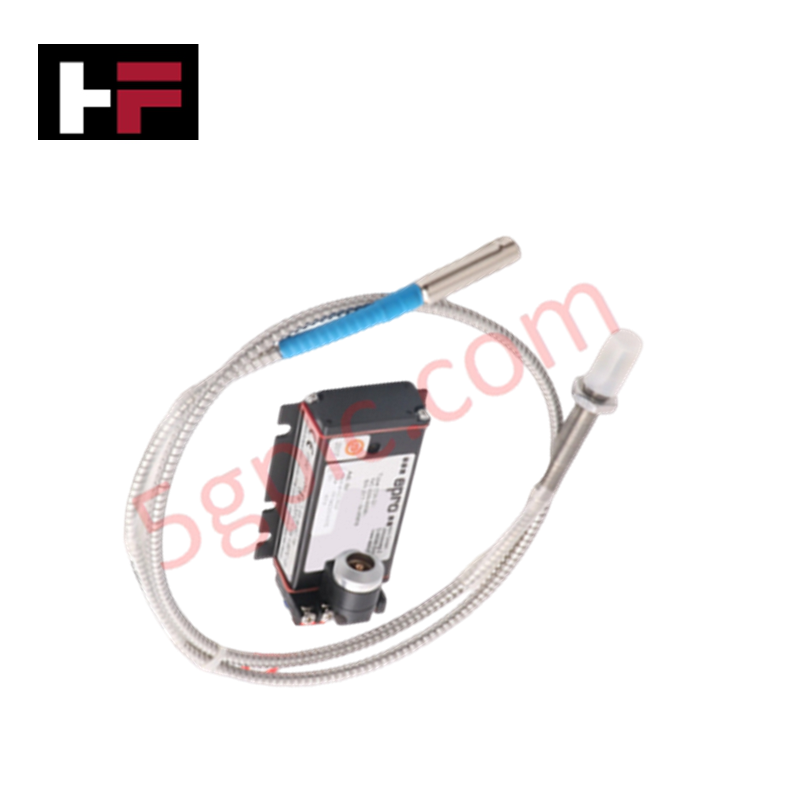
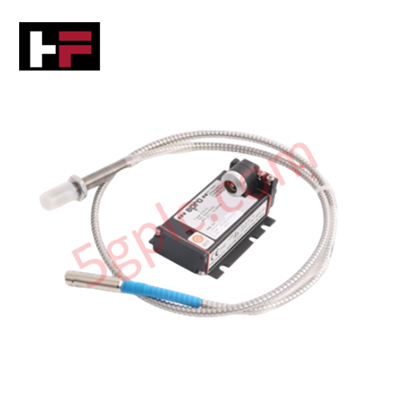
Configured for rotational velocity acquisition in industrial machinery, the Epro PR9376/010-001 (PR9376/010-001) Hall-Effect Speed and Proximity Sensor provides direct electrical execution of non-contact pulse generation from rotating ferromagnetic targets.
Hardware Specifications
| Parameter | Specification |
|---|---|
| Model | PR9376/010-001 |
| Brand | Epro |
| Origin | Germany |
| Operating Temp | -25 deg C to +100 deg C |
| Power Consumption | <= 25 mA (10-30 VDC) |
| Output | Digital pulse (High >10 V / Low <1 V) |
| Frequency Capability | Up to 12 kHz |
| Air Gap | 1.0 mm to 1.5 mm |
Mechanical Monitoring and TSI Characteristics
The PR9376/010-001 utilizes Hall-effect magnetic detection to monitor shaft speed by tracking the passage of gear teeth or keyways. To ensure signal fidelity, maintain the specified air gap strictly; deviation from the 1.0 mm or 1.5 mm tolerance will degrade pulse amplitude and timing accuracy. In multi-sensor TSI arrays, ensure proper cable routing to prevent cross-talk between high-speed signal channels, as external electromagnetic interference can distort transition characteristics. The sensor output provides 1 AC cycle per gear tooth pass, requiring a clean ferromagnetic target surface to avoid pulse dropout or erratic switching.
Frequently Asked Questions
Q: Is the 12 kHz frequency capability sufficient for all turbine applications?
A: The 12 kHz limit covers most standard industrial applications. For high-speed rotors with high-tooth-count gears, ensure the calculated pulse frequency does not exceed the sensor's bandwidth to prevent pulse skipping or output saturation.
Q: How should the sensor be oriented relative to the gear teeth?
A: The sensor must be mounted perpendicular to the target surface. The active tip must face the ferromagnetic material directly to achieve the magnetic flux variation required to trigger the Hall-effect switch logic.
Field Installation Guidelines
- Ensure the mounting bracket is rigid to avoid vibration-induced changes to the air gap, which can cause intermittent signal loss.
- Terminate the cable at the monitoring system input; ensure the shield is connected at the control cabinet side to mitigate electromagnetic interference.
- Check the target material properties; ensure it is a soft magnetic steel to maintain optimal flux density for the Hall-effect element.
- Verify the power supply voltage is within the 10-30 VDC range.
- Perform a commissioning test by manually rotating the shaft at low speed to confirm square wave pulse generation before applying full operational velocity.
Additional Information
- 100% Genuine Parts: All products are original and authentic, ensuring reliable industrial performance.
- 30-Day Refund Guarantee: Return any in-stock item within 30 days in original, unopened packaging for a full refund (excluding shipping and fees).
- 12-Month Warranty: Covers defects in materials or workmanship; excludes misuse, normal wear, or unauthorized modifications.
- Worldwide Shipping: We ship via USPS, UPS, FedEx, and DHL. Delivery times vary by country and may be subject to customs or import fees.
- Support & Contact: Technical and warranty assistance is available anytime. Contact us here: Contact.
- Purchase Guidance: Check product specifications and compatibility carefully before ordering to ensure proper application.




Tech & Buying Guide

Demystifying the DDE Protocol in Legacy Industrial Automation Systems
Modern control systems rely heavily on seamless interprocess communication to exchange operational data between software programs. Microsoft first introduced the Dynamic Data Exchange (DDE) protocol in 1987 to enable real-time data sharing. In factory automation, DDE served as an early bridge between control software and Windows desktop applications. Therefore, understanding DDE mechanics provides crucial insights into how legacy industrial networks established software-level connectivity.

Demystifying CPU Communication Ports in Siemens PLC Architectures
Industrial automation relies heavily on robust data exchange between devices. Without seamless connectivity, field instruments, network switches, human-machine interfaces, and programmable logic controllers cannot coordinate effectively. Therefore, understanding the various CPU communication ports available in Siemens hardware ensures efficient factory automation design and seamless system integration.

Mastering the Siemens PLC Scan Cycle: How the CPU Executes Automation Programs
Industrial automation relies heavily on programmable logic controllers (PLCs) to manage complex manufacturing processes. Many engineers dive straight into programming without mastering the underlying architecture. However, understanding how a PLC CPU executes a program ensures reliable system design. Therefore, mastering the scan cycle optimizes both performance and troubleshooting in modern control systems.