










Product Details
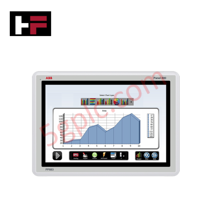
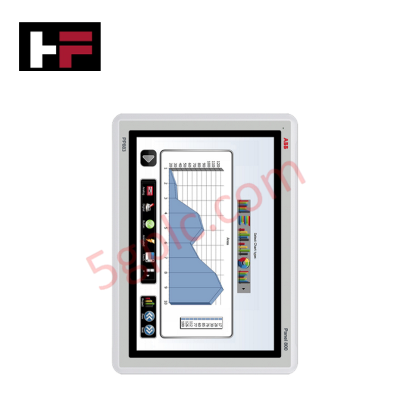
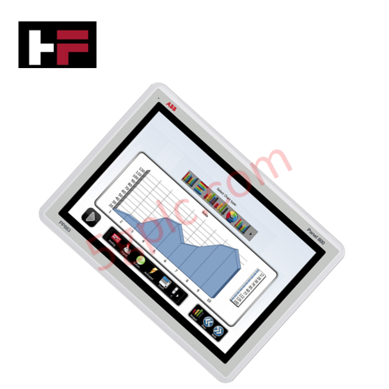
Configured for industrial human-machine interfacing and local terminal monitoring in automated plant nodes, the ABB PP875 3BSE092977R1 (PP875 Standard Panel 7") provides direct physical/electrical execution.
Hardware Specifications
| Parameter | Specification |
|---|---|
| Model | PP875 3BSE092977R1 |
| Brand | ABB |
| Origin | Sweden |
| Weight | 0.8 kg net |
| Dimensions | 204 mm x 143 mm x 50 mm (Cut-out: 187 mm x 126 mm) |
| Operating Temp | -10 deg C to +60 deg C (Storage: -20 deg C to +70 deg C) |
| Power Consumption | 14.4 W |
| Display Type / Size | Resistive touch / 7 inch (16:9 ratio) |
| Resolution / Brightness | 800 x 480 pixels / 350 cd/m2 (with dimming support) |
| Processor / Main Memory | ARM9 (1 GHz) / 512 MB |
| External Storage Media | 2 GB SSD (1.5 GB allocated for application storage) |
| Power Supply | +24 VDC (18 to 32 VDC allowable range) |
| Ethernet Interface | 1 x 10/100 Base-T (Shielded RJ45) |
| USB Port | 1 x USB 2.0 (500 mA maximum) |
| Serial Interfaces | 1 x RS232, 1 x RS422/485, 1 x RS485 (dependent on COM2 configuration) |
| Housing Protection | Front: IP65, NEMA 4X/12, UL Type 4X/12. Rear: IP20 |
| Enclosure Material | White powder-coated aluminum frame with front foil |
| Vibration / Shock Limits | 1 G / 15 G |
| Certifications | CE, FCC, KCC, UL 61010-2-201, Marine (DNV, KR, GL, LR, ABS, CCS) |
Firmware Flash Compatibility and Deterministic Networks
The PP875 runs an integrated operating platform driven by a 1 GHz ARM9 processor, requiring precise firmware flash compatibility verification during multi-node interface synchronization. The runtime architecture communicates over its shielded 10/100 Base-T Ethernet port to interface with external master automation layers. This topology aligns data structures across EtherNet/IP deterministic networks, maintaining deterministic update latencies during sustained data packet bursts. Internal system flash memory fields isolate runtime telemetry parameters from base system images, protecting local configuration maps and protocol driver tables from degradation during unexpected power drops across the 24 VDC feeder line.
Frequently Asked Questions
Q: How does the internal runtime software handle a mismatch in firmware flash compatibility during a project download?
A: When a project file contains runtime binaries that do not align with the baseline OS version stored in the internal flash, the panel halts execution and returns a firmware verification fault. System operators must flash matching image versions using the loader tool to re-establish proper driver execution and boot sequences.
Q: Is hot-swapping or unpowered removal of the external storage media safe during ongoing runtime application writes?
A: Unpowering or removing external storage nodes during active write loops creates risk of flash partition corruption. Data write operations must be completed or programmatically isolated within the HMI application architecture prior to servicing the memory components.
Field Installation Guidelines
- Mechanical Panel Cut-out Realization: Prepare a mounting aperture inside the enclosure door measuring exactly 187 mm by 126 mm. Insert the unit through the front opening, ensuring the perimeter sealing gasket sits flush against the plate to maintain the IP65 and NEMA 4X front protection ratings.
- Mounting Fastener Torque Enforcement: Secure the device using the integrated panel mount clamps or a VESA 75 x 75 framework. Tighten all retention hardware evenly to compress the front foil gasket without warping the aluminum frame layout. Maintain a minimum rear clearance depth of 143 mm for cable paths and thermal air dissipation.
- Power Supply and Field Grounding: Connect a dedicated 24 VDC source to the power terminals, observing the 18 to 32 VDC operating boundaries. Connect the chassis ground terminal directly to the panel instrumentation grounding bus using a short, low-impedance copper lead to mitigate external electrical interference.
- Communication Cable Routing Constraints: Run the shielded RJ45 Ethernet cable and serial bus connections (RS232/RS422/RS485) through separate wiring wireways away from high-voltage AC electric lines or variable frequency drive loops to comply with standard UL 61010-2-201 separation parameters.
Additional Information
- 100% Genuine Parts: All products are original and authentic, ensuring reliable industrial performance.
- 30-Day Refund Guarantee: Return any in-stock item within 30 days in original, unopened packaging for a full refund (excluding shipping and fees).
- 12-Month Warranty: Covers defects in materials or workmanship; excludes misuse, normal wear, or unauthorized modifications.
- Worldwide Shipping: We ship via USPS, UPS, FedEx, and DHL. Delivery times vary by country and may be subject to customs or import fees.
- Support & Contact: Technical and warranty assistance is available anytime. Contact us here: Contact.
- Purchase Guidance: Check product specifications and compatibility carefully before ordering to ensure proper application.
Tech & Buying Guide

Engineering Guide: Power Supply Sizing for PLC and DCS Control Systems

Interface Philosophy Between DCS and Motor Control Centers in Industrial Automation

Batch vs Continuous Processing in Industrial Automation: Architectural Strategies for Control Engineers
Selecting the proper control architecture remains a pivotal decision when designing industrial automation systems. Automation engineers must evaluate whether a batch or continuous process model best fits their production requirements. This fundamental choice influences PLC and DCS programming, hardware redundancy, sensor selection, and overall factory automation layouts.