










Product Details
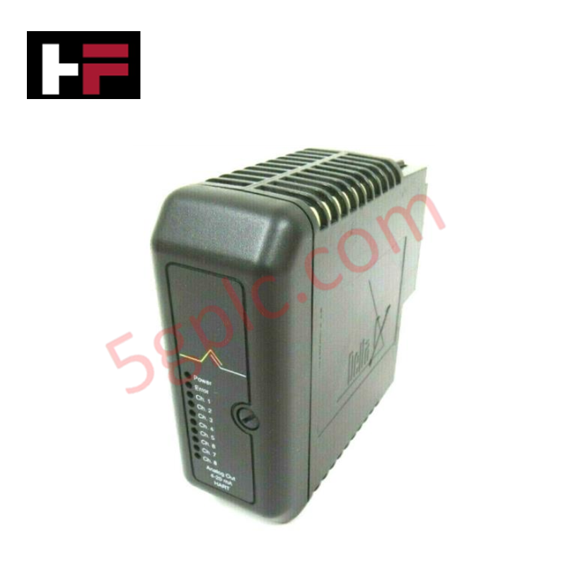
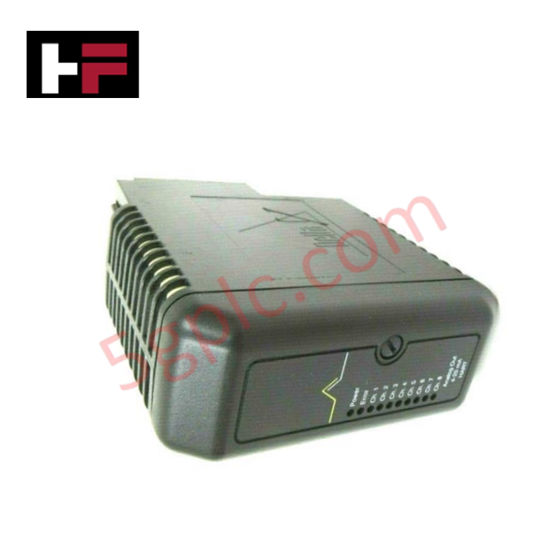
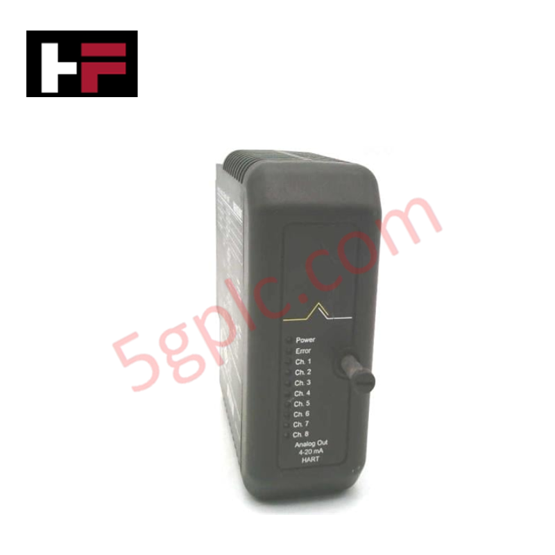
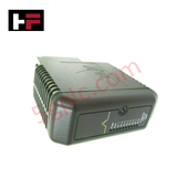
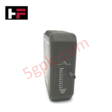
The Emerson KJ3222X1-BA2 serves as the primary KJ3222X1-BA2 Analog Input Module utilized to execute continuous instrumentation monitoring across DeltaV distributed control system platforms. This 8-channel physical interface unit converts analog loop current variations into scaled internal values, transmitting the processed instrumentation data directly across the backplane bus interface for real-time computational execution.
Hardware Specifications
| Parameter | Specification |
| Model | KJ3222X1-BA2 |
| Brand | Emerson |
| Origin | USA |
| Weight | 0.2 kg (0.44 lbs) |
| Dimensions | 4.4 cm x 10.8 cm x 12.7 cm (1.73 in x 4.25 in x 5.00 in) |
| Operating Temp | -40 deg C to +70 deg C |
| Power Consumption | 12 VDC at 150 mA (Standard local bus draw allocation) |
| Input Channel Count | 8 channels |
| Input Signal Configuration | 4-20 mA HART loop protocol |
| Isolation Specification | Channel-to-channel isolation parameters enforced |
Channel-to-Channel Isolation Layer
Mechanical execution of this 8-channel acquisition module relies on internal hardware barriers to safeguard instrumentation signal tracks. The architecture provides strict channel-to-channel isolation layers coupled with dedicated data filtering arrays. This layout stops local ground loops, transient voltage spikes, or single-loop short circuits from transferring into adjacent measuring paths, preserving digital telemetry data streams passed via the superimposed 4-20 mA HART loop protocol.
Frequently Asked Questions
Q: Does this analog input card support continuous hot-swap procedures inside an active rack carrier?
A: Yes. The hardware is designed for online replacement, allowing live module extraction and insertion into an energized slot without creating bus interruptions or altering data processing functions on surrounding operational units.
Q: How does the module handle combined digital and analog signals on a single channel wire run?
A: The input circuitry uses a low-pass filter array to extract the standard 4-20 mA analog value while concurrently decoupling the high-frequency FSK digital bitstream to maintain simultaneous HART telemetry processing.
Field Installation Guidelines
-
Carrier Baseplate Insertion: Position the module tracks over the matching alignment ribs on the designated S-Series interface carrier slot. Apply steady inward pressure until the mechanical mounting clips seat entirely into the base assembly.
-
Shield Continuity Terminations: Route and terminate all external transmitter cable shields directly at the common cabinet earth ground bar. Implementing a single-point grounding matrix stops low-frequency common-mode voltage noise from skewing loop measurements.
-
Conductor Separation Standards: Group and route all 4-20 mA instrumentation loops in independent paths separated from high-voltage AC electrical lines by a minimum layout distance of 300 mm to suppress electro-magnetic coupling.
-
Atmospheric Sealing Controls: For factory floor installations showing high ambient particulate loads, place the control chassis inside an industrial enclosure matching standard positive-pressure rules to maintain operational limits.
Additional Information
- 100% Genuine Parts: All products are original and authentic, ensuring reliable industrial performance.
- 30-Day Refund Guarantee: Return any in-stock item within 30 days in original, unopened packaging for a full refund (excluding shipping and fees).
- 12-Month Warranty: Covers defects in materials or workmanship; excludes misuse, normal wear, or unauthorized modifications.
- Worldwide Shipping: We ship via USPS, UPS, FedEx, and DHL. Delivery times vary by country and may be subject to customs or import fees.
- Support & Contact: Technical and warranty assistance is available anytime. Contact us here: Contact.
- Purchase Guidance: Check product specifications and compatibility carefully before ordering to ensure proper application.




Tech & Buying Guide

Understanding VFD Mechanical Brake Logic and Control in Industrial Automation
Variable Frequency Drives (VFDs) play a crucial role in modern industrial automation by controlling motor speed, torque, and acceleration. However, high-inertia loads and vertical lifting systems require precise mechanical braking logic to ensure operational safety and prevent equipment damage.

Why Programmable Logic Controllers Drop into Stop Mode: An Expert Analysis
Industrial automation systems rely heavily on Programmable Logic Controllers (PLCs) to maintain uninterrupted production. When a PLC unexpectedly shifts from Run to Stop mode, whole manufacturing lines stall.
As control systems evolve across modern factory automation, understanding the root causes of these interruptions helps engineers minimize costly downtime. This technical guide breaks down why PLCs trip into Stop mode and provides practical strategies to mitigate system faults.

Understanding Root Causes of Unplanned PLC Stop Mode in Industrial Automation
Modern Programmable Logic Controllers manage execution through distinct operational states: Run, Stop, Start-Up, and Hold. During power-up, a controller initializes memory registers within Stop mode before briefly transitioning to Start-Up mode. During this phase, internal self-diagnostics evaluate system integrity across hardware and user programs. If the controller detects no critical faults, it enters Run mode to execute the control program continuously. However, any severe system anomaly forces the CPU back into Stop mode immediately to prevent erratic machine behavior across the plant floor.