


Product Details
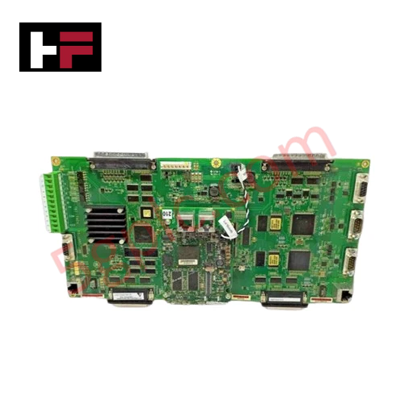
Configured for multi-function signal management in power generation control architectures, the GE IS210MACCH2AFG (IS210MACCH2AFG Multi-Function I/O Controller) provides direct physical and electrical execution of turbine function monitoring and industrial communication.
Hardware Specifications
| Parameter | Specification |
|---|---|
| Model | IS210MACCH2AFG |
| Brand | GE Energy |
| Origin | USA |
| Weight | Standard PCB assembly |
| Dimensions | 100 mm x 100 mm x 25 mm |
| Operating Temp | -40 deg C to 70 deg C |
| Power Consumption | 24 VDC nominal |
| Communication | RS485 Interface |
| Core Function | Application converter control |
Profinet / EtherNet/IP Deterministic Networks
The IS210MACCH2AFG serves as a modular controller within the turbine control ecosystem, leveraging backplane bus communication velocity to process localized application converter logic. The unit incorporates an RS485 interface to facilitate serial data exchange, ensuring deterministic performance when interfacing with peripheral instrumentation. Firmware flash compatibility is dictated by the specific GE Energy control platform revision; verify that the host controller’s software version aligns with the hardware implementation to prevent communication mismatches. The architecture supports I/O density scaling via the integration of secondary controller boards, allowing for the expansion of turbine monitoring parameters while maintaining the timing integrity required for converter control loops.
Frequently Asked Questions
Q: Does the IS210MACCH2AFG support hot-swap replacement in an energized chassis?
A: No. Replacement of the PCB must be performed while the control rack is de-energized. Inserting or removing the module under power risks damage to the backplane connectors and potential corruption of the active control state.
Q: What is the primary function of the RS485 serial interface on this board?
A: The RS485 interface is designated for communication with external industrial devices and peripheral sensors, allowing the module to exchange data streams outside of the primary backplane network while maintaining signal consistency.
Field Installation Guidelines
- Mounting: Secure the board within the control chassis using the provided mounting points. Ensure proper orientation to facilitate backplane alignment and airflow through the module assembly.
- Wiring: Use shielded RS485 communication cabling to prevent electromagnetic interference. Ensure that the cable shield is terminated at the designated cabinet grounding point to protect data integrity.
- Powering: Verify the input voltage is stable at 24 VDC before activating the power rail. Improper voltage levels may cause intermittent reset loops or failure of the internal signal processing circuitry.
- Integration: Upon installation, confirm the module is correctly identified in the control software. Perform a signal loop test on the application converter control channels to ensure that output parameters reflect the expected physical turbine state.
- Environment: While the module is rated for -40 deg C to 70 deg C, maintain the cabinet climate control systems to prevent the accumulation of moisture, which could lead to conductive pathways across the PCB surface.
Additional Information
- 100% Genuine Parts: All products are original and authentic, ensuring reliable industrial performance.
- 30-Day Refund Guarantee: Return any in-stock item within 30 days in original, unopened packaging for a full refund (excluding shipping and fees).
- 12-Month Warranty: Covers defects in materials or workmanship; excludes misuse, normal wear, or unauthorized modifications.
- Worldwide Shipping: We ship via USPS, UPS, FedEx, and DHL. Delivery times vary by country and may be subject to customs or import fees.
- Support & Contact: Technical and warranty assistance is available anytime. Contact us here: Contact.
- Purchase Guidance: Check product specifications and compatibility carefully before ordering to ensure proper application.


Tech & Buying Guide

Essential Motion Control Commands: A Practical Guide for Engineers
Automation engineers often rely on precise position and speed control to drive modern factory machinery. Modern industrial systems, such as Programmable Logic Controllers (PLCs) and Distributed Control Systems (DCS), depend heavily on standardized motion instructions. Mastering these commands ensures operational safety, protects mechanical components, and optimizes cycle times across production lines.

The Role of Intrinsic Safety Barriers in PLC and DCS Architectures
Implementing robust protection in hazardous industrial environments represents a fundamental safety requirement in factory automation. Process facilities often handle volatile gases, dusts, and chemical agents that pose significant combustion risks. Consequently, control system engineers must deploy energy-limiting interfaces to isolate safe-area control cabinets from hazardous-area field instrumentation. This article examines the function, selection, and electrical principles of intrinsic safety barriers within modern PLC and DCS networks.

Architectural Selection and Scale Classification of PLC Systems in Industrial Automation
Selecting the correct control platform represents a foundational engineering decision in factory automation. System designers must carefully balance technical parameters against long-term operational requirements when implementing a Programmable Logic Controller (PLC). This article examines the critical evaluation metrics, physical scale classifications, and operational architectures of modern control systems.