


Product Details
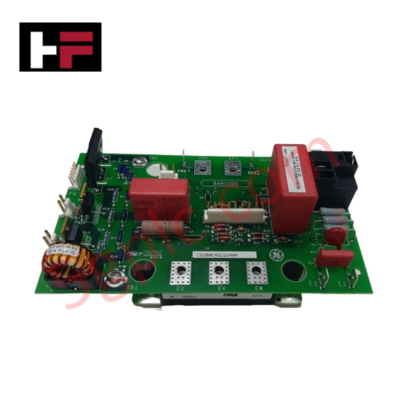
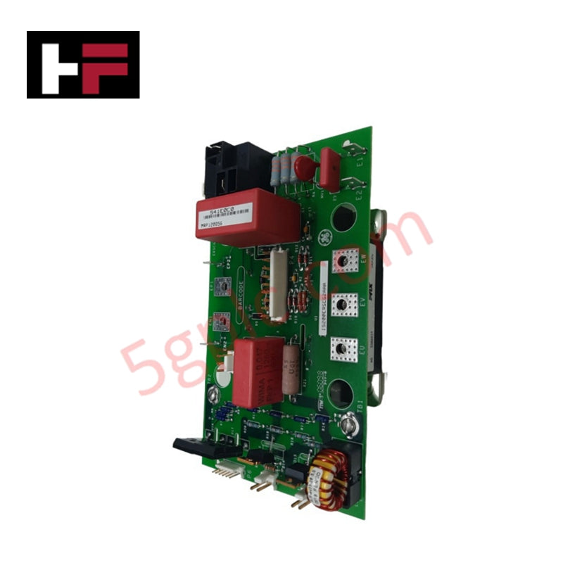
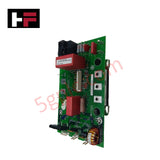
Configured for pulse-width-modulated DC current generation in EX2100 excitation control systems, the GE IS200ERSCG2A (IS200ERSCG2A Regulator Static Converter Board) provides direct physical and electrical execution of field excitation and discharge control.
Hardware Specifications
| Parameter | Specification |
|---|---|
| Model | IS200ERSCG2A |
| Brand | General Electric |
| Origin | USA |
| Weight | Standard PCB assembly |
| Dimensions | EX2100 standard form factor |
| Operating Temp | Industrial rated range |
| Power Consumption | System-bus dependent |
| Technology | Surface Mount / IGBT |
| Output Type | PWM DC Current |
Backplane Bus Communication Velocity Licences
The IS200ERSCG2A functions as a high-speed converter interface within the EX2100 architecture, facilitating deterministic control signal exchange with ERIO, ERDD, ERRR, ERRB, and ERBP modules. The board utilizes integrated IGBTs to achieve precise PWM DC output current regulation, while maintaining backplane bus communication velocity compatibility for synchronized excitation control. Firmware flash compatibility is governed by the host excitation controller to ensure timing alignment with turbine operation requirements. I/O density scaling is managed through modular interconnection, allowing the converter board to operate in both simplex and redundant configurations while maintaining real-time response for field discharge and DC-link bypass relay functions.
Frequently Asked Questions
Q: Is the IS200ERSCG2A module capable of hot-swap during excitation system operation?
A: No. Any maintenance or replacement requires the excitation system to be de-energized and verified to a zero-energy state to prevent accidental discharge or IGBT damage.
Q: Can the internal relay bypass be controlled by an external DCS?
A: The relay function is managed by the EX2100 regulator logic. While the system can communicate with a standalone DCS via Modbus, direct relay control is constrained by the board's internal safety and discharge protocols.
Field Installation Guidelines
- Mounting: Secure the board in the EX2100 control cabinet chassis. Ensure all interface connectors to auxiliary modules (ERIO/ERDD) are firmly seated to prevent signal jitter.
- Wiring: Ensure high-current paths for the DC output are terminated using specified cable gauges to minimize voltage drop. Verify that the field discharge circuit is correctly wired to the board's designated terminals.
- Grounding: Bond the board's chassis to the cabinet grounding bus. Proper low-impedance grounding is required to stabilize the PWM reference and mitigate electromagnetic noise from IGBT switching.
- Environment: Operate the module within the rated cabinet temperature limits. Ensure that cooling airflow is unobstructed, particularly around the IGBT heatsink assemblies.
- Verification: Prior to startup, perform an impedance check on the DC-link charging resistor bypass circuit. Use the EX2100 diagnostic terminal to confirm software-to-hardware communication and relay functional integrity.
Additional Information
- 100% Genuine Parts: All products are original and authentic, ensuring reliable industrial performance.
- 30-Day Refund Guarantee: Return any in-stock item within 30 days in original, unopened packaging for a full refund (excluding shipping and fees).
- 12-Month Warranty: Covers defects in materials or workmanship; excludes misuse, normal wear, or unauthorized modifications.
- Worldwide Shipping: We ship via USPS, UPS, FedEx, and DHL. Delivery times vary by country and may be subject to customs or import fees.
- Support & Contact: Technical and warranty assistance is available anytime. Contact us here: Contact.
- Purchase Guidance: Check product specifications and compatibility carefully before ordering to ensure proper application.


Tech & Buying Guide

Essential Motion Control Commands: A Practical Guide for Engineers
Automation engineers often rely on precise position and speed control to drive modern factory machinery. Modern industrial systems, such as Programmable Logic Controllers (PLCs) and Distributed Control Systems (DCS), depend heavily on standardized motion instructions. Mastering these commands ensures operational safety, protects mechanical components, and optimizes cycle times across production lines.

The Role of Intrinsic Safety Barriers in PLC and DCS Architectures
Implementing robust protection in hazardous industrial environments represents a fundamental safety requirement in factory automation. Process facilities often handle volatile gases, dusts, and chemical agents that pose significant combustion risks. Consequently, control system engineers must deploy energy-limiting interfaces to isolate safe-area control cabinets from hazardous-area field instrumentation. This article examines the function, selection, and electrical principles of intrinsic safety barriers within modern PLC and DCS networks.

Architectural Selection and Scale Classification of PLC Systems in Industrial Automation
Selecting the correct control platform represents a foundational engineering decision in factory automation. System designers must carefully balance technical parameters against long-term operational requirements when implementing a Programmable Logic Controller (PLC). This article examines the critical evaluation metrics, physical scale classifications, and operational architectures of modern control systems.