


Product Details
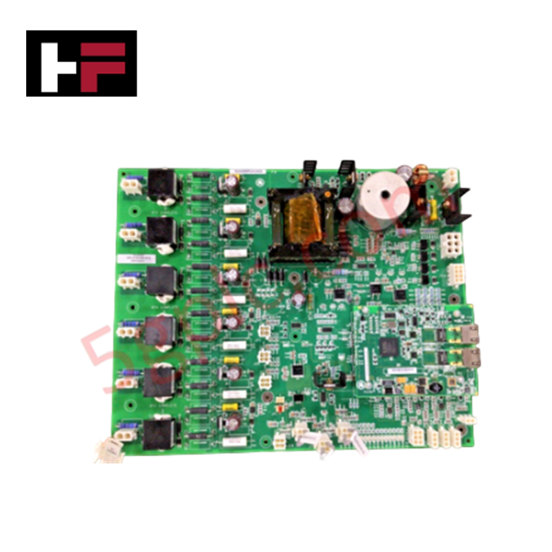
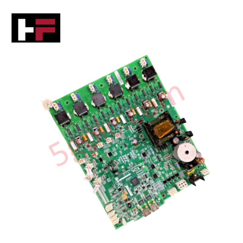
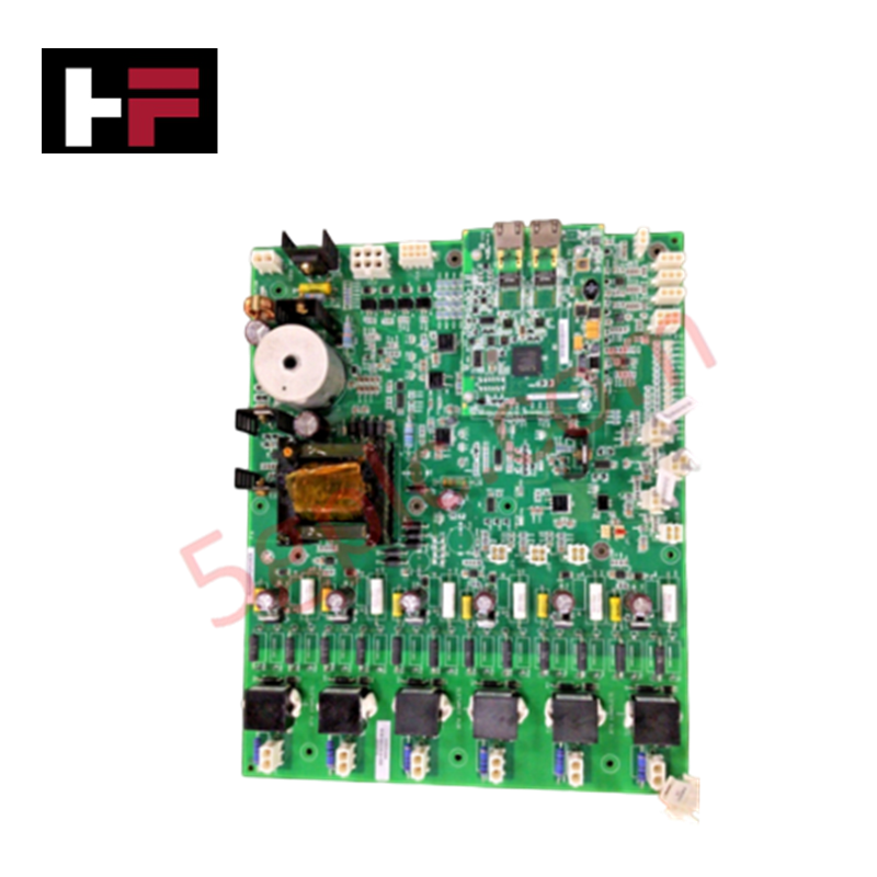
Configured for thyristor control in EX2100e excitation systems, the GE IS200EBRGH2A (IS200EBRGH2A Exciter Bridge Interface Board) provides direct physical and electrical execution of gate firing signal processing and bridge feedback monitoring.
Hardware Specifications
| Parameter | Specification |
|---|---|
| Model | IS200EBRGH2A |
| Brand | General Electric |
| Origin | USA |
| Weight | 2 lbs (0.91 kg) |
| Dimensions | 10.2 x 5.1 cm |
| Operating Temp | 0 to 60 deg C |
| Power Consumption | 125 VDC nominal |
| Analog Output | 0-20 mA |
| Compatibility | 42, 52, and 77 mm Thyristor Systems |
V/Hz and Field-Oriented Vector Control
The IS200EBRGH2A acts as a critical interface layer between the control processor and the power bridge, ensuring precise regulation of excitation current. By facilitating gate command distribution, the board supports the internal algorithms necessary for V/Hz and field-oriented vector control strategies within the generator excitation loop. The module is engineered to support various thyristor frame sizes (42 mm, 52 mm, and 77 mm), allowing for flexible adaptation to different power bridge architectures. Accurate actuator loop feedback response is maintained through the 0-20 mA analog output stage, ensuring synchronization between the exciter output and generator field requirements. The surface-mount technology utilized on the PCB minimizes parasitic inductance, reducing potential interference in high-speed gate pulse generation.
Frequently Asked Questions
Q: Can this board be used for thyristor systems outside of the specified 42 mm to 77 mm range?
A: No. The hardware is specifically indexed for compatibility with 42, 52, and 77 mm thyristor architectures. Use with incompatible bridge frame sizes may result in improper firing sequences or gate trigger failure.
Q: Is this board compatible with standard 24 VDC control power?
A: No. The IS200EBRGH2A requires a 125 VDC nominal power supply to operate its gate drive circuitry and bridge interface logic. Verification of the power supply voltage is necessary before energizing the board.
Field Installation Guidelines
- Mounting: Secure the board within the exciter bridge cabinet. Ensure the mounting standoffs provide adequate clearance from the power bridge busbars to prevent arcing or insulation degradation.
- Wiring: Use high-temperature, shielded signal wiring for all gate pulse connections. Maintain strict separation between low-voltage feedback signals and high-power DC/AC excitation lines to minimize EMI.
- Inspection: Prior to installation, confirm the thyristor system size matches the configuration of the IS200EBRGH2A. Inspect all connector pins for deformation or oxidation.
- Integration: Verify the 125 VDC supply polarity before connecting the power input. Once seated, perform a cold-loop check using the EX2100e diagnostic software to ensure all gate pulse channels communicate correctly with the main controller.
- Environment: Ensure the exciter cabinet cooling system is functional. The board is rated for 0 to 60 deg C; exceeding these limits can lead to thermal drift in the analog 0-20 mA feedback loop, causing excitation instability.
Additional Information
- 100% Genuine Parts: All products are original and authentic, ensuring reliable industrial performance.
- 30-Day Refund Guarantee: Return any in-stock item within 30 days in original, unopened packaging for a full refund (excluding shipping and fees).
- 12-Month Warranty: Covers defects in materials or workmanship; excludes misuse, normal wear, or unauthorized modifications.
- Worldwide Shipping: We ship via USPS, UPS, FedEx, and DHL. Delivery times vary by country and may be subject to customs or import fees.
- Support & Contact: Technical and warranty assistance is available anytime. Contact us here: Contact.
- Purchase Guidance: Check product specifications and compatibility carefully before ordering to ensure proper application.


Tech & Buying Guide

Essential Motion Control Commands: A Practical Guide for Engineers
Automation engineers often rely on precise position and speed control to drive modern factory machinery. Modern industrial systems, such as Programmable Logic Controllers (PLCs) and Distributed Control Systems (DCS), depend heavily on standardized motion instructions. Mastering these commands ensures operational safety, protects mechanical components, and optimizes cycle times across production lines.

The Role of Intrinsic Safety Barriers in PLC and DCS Architectures
Implementing robust protection in hazardous industrial environments represents a fundamental safety requirement in factory automation. Process facilities often handle volatile gases, dusts, and chemical agents that pose significant combustion risks. Consequently, control system engineers must deploy energy-limiting interfaces to isolate safe-area control cabinets from hazardous-area field instrumentation. This article examines the function, selection, and electrical principles of intrinsic safety barriers within modern PLC and DCS networks.

Architectural Selection and Scale Classification of PLC Systems in Industrial Automation
Selecting the correct control platform represents a foundational engineering decision in factory automation. System designers must carefully balance technical parameters against long-term operational requirements when implementing a Programmable Logic Controller (PLC). This article examines the critical evaluation metrics, physical scale classifications, and operational architectures of modern control systems.