












Product Details
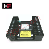
The Honeywell Q7800A1005, also cataloged as the Q7800A1005/B Universal Wiring Subbase, operates as a dedicated hardware component for surface mounting and external electrical terminal interface execution within 7800 Series burner control platforms.
Suffix Breakdown & Model Matrix
The 7800 Series wiring subbases utilize structural suffix designators to specify physical configuration and terminal assembly layout:
- Q7800A: Universal wiring subbase designed for panel mounting with accessible terminal connections.
- Q7800B: Internal cabinet subbase structure for specialized enclosure integrations.
- Suffix /B: Designates the secondary revision release indicating physical material validation and compliance updates without altering terminal assignments or mechanical footprint.
Hardware Specifications
| Parameter | Specification |
|---|---|
| Model | Q7800A1005 (Ordering Part: Q7800A1005/B) |
| Brand | Honeywell |
| Origin | USA |
| Weight | 1.43 lbs (0.65 kg) |
| Dimensions | 127 mm x 127 mm x 38 mm |
| Operating Temp | -40 deg C to +60 deg C |
| Power Consumption | Passive wiring interface (0 W internal load) |
| Terminal Count | 22 knife-blade terminals |
| Mounting Orientation | Wall or panel mount (2-sided accessibility) |
| Voltage Rating | 120 VAC / 240 VAC (50/60 Hz) |
Backplane Communication & I/O Density Scaling
The subbase acts as the structural interface for 7800 Series modules, facilitating deterministic signal routing and physical backplane interconnection between line-voltage field sensors, flame detectors, and the main control module. The 22-terminal layout enforces high I/O density scaling within a compact footprint, allowing dual-sided wiring access to separate line-voltage ignition circuits from low-voltage flame signal runs. Integrated terminal barriers prevent physical cross-shorting and maintain dielectric integrity during high-voltage ignition transients up to 10 kV.
Frequently Asked Questions
Q: Can the Q7800A1005 subbase be wired and tested before installing the 7800 Series burner control module?
A: Yes. The subbase features passive knife-blade contact terminals that allow full field wiring, continuity checks, and line-voltage validation prior to plugging in the active relay module or purger controls.
Q: What screw torque specification is required for the 22 field terminals?
A: Field wiring screws must be tightened to a torque of 0.8 Nm to 1.1 Nm (7 to 10 lb-in) to ensure solid low-resistance contact and prevent thermal hot spots during high-current burner sequence operations.
Field Installation Guidelines
- Mounting Surface Setup: Secure the subbase to a flat, grounded vertical panel using four No. 6 pan-head screws through the pre-cast corner mounting slots.
- Wiring Separation: Route high-voltage ignition and motor wires through separate conduit entries away from low-voltage flame detector leads to mitigate electromagnetic interference (EMI).
- Conductor Gauge: Use copper conductors rated for a minimum of 90 deg C. Terminal clamps accept single or dual 14 AWG to 18 AWG solid or stranded wire runs.
- Shield Grounding: Connect all flame signal cable shields to a single grounding point at the subbase chassis earth terminal. Do not ground the shield at the sensor head end to prevent ground loop currents.
Additional Information
- 100% Genuine Parts: All products are original and authentic, ensuring reliable industrial performance.
- 30-Day Refund Guarantee: Return any in-stock item within 30 days in original, unopened packaging for a full refund (excluding shipping and fees).
- 12-Month Warranty: Covers defects in materials or workmanship; excludes misuse, normal wear, or unauthorized modifications.
- Worldwide Shipping: We ship via USPS, UPS, FedEx, and DHL. Delivery times vary by country and may be subject to customs or import fees.
- Support & Contact: Technical and warranty assistance is available anytime. Contact us here: Contact.
- Purchase Guidance: Check product specifications and compatibility carefully before ordering to ensure proper application.




Tech & Buying Guide

Redefining Control Systems: The Rise of Flexible I/O Modules in Industrial Automation
Conventional input-output architectures often limit engineering agility and inflate long-term inventory costs. Today, Flexible Input/Output Modules (FIOM) are transforming how control system engineers design, commission, and maintain automation infrastructure. By allowing individual channel software configuration, FIOM technology bridges the gap between rigid hardware design and dynamic plant requirements.

Understanding Modern SCADA Systems: Architecture, Communication Topologies, and Industrial Applications
Supervisory Control and Data Acquisition (SCADA) systems form the digital backbone of modern industrial automation. They collect critical field data, transmit signals across vast distances, and empower plant operators with real-time process visibility. Across modern infrastructures, SCADA solutions streamline centralized control and maintain continuous operational uptime.
Understanding OPC Servers in Modern Industrial Automation: Principles, Architecture, and Applications
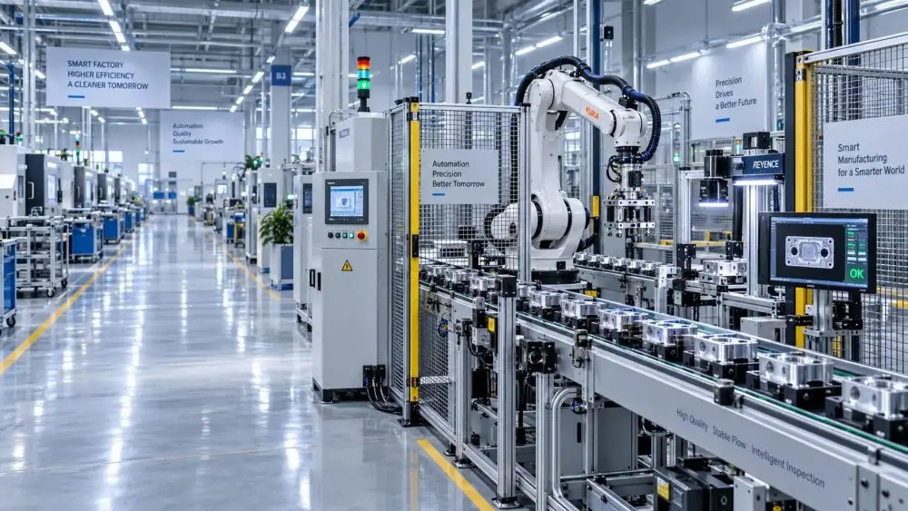
In industrial automation, connecting physical hardware with high-level software remains a primary operational challenge. Factories utilize programmable logic controllers (PLCs), distributed control systems (DCS), human-machine interfaces (HMIs), and smart sensors from diverse vendors. These devices often speak different proprietary protocols. Open Platform Communications (OPC) servers solve this interoperability challenge by standardizing how data flows across factory networks.