










Product Details
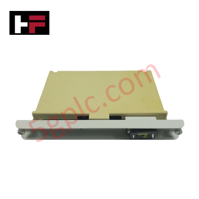
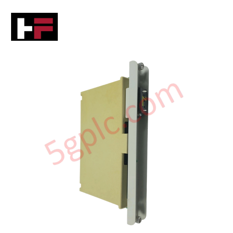
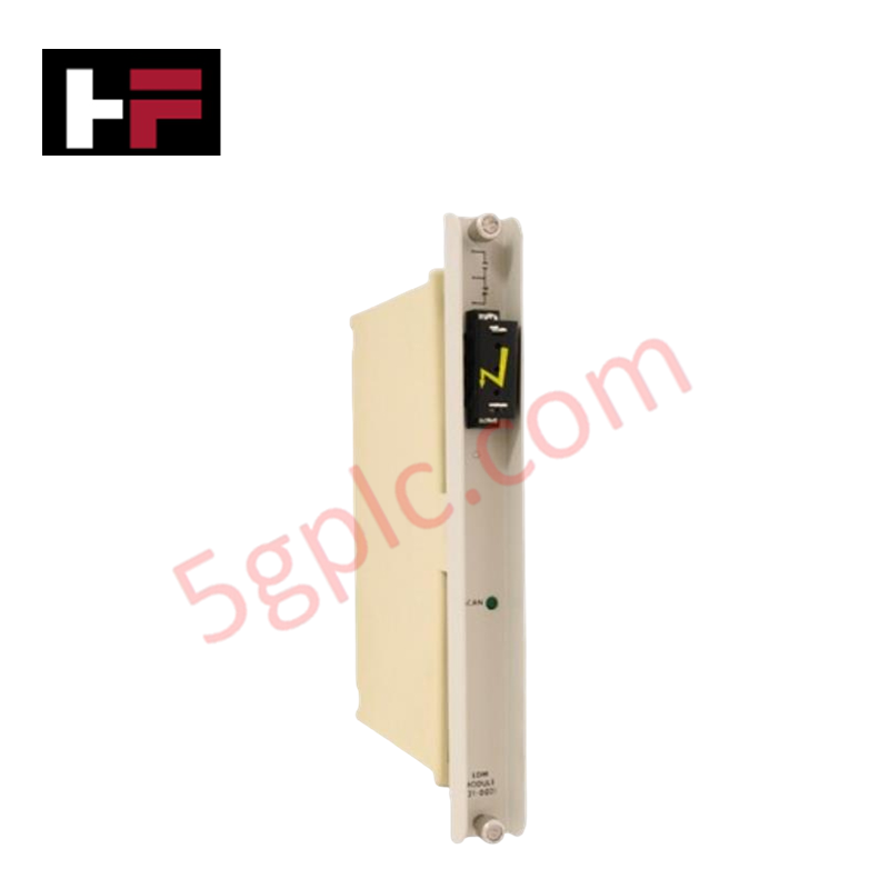
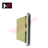
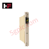
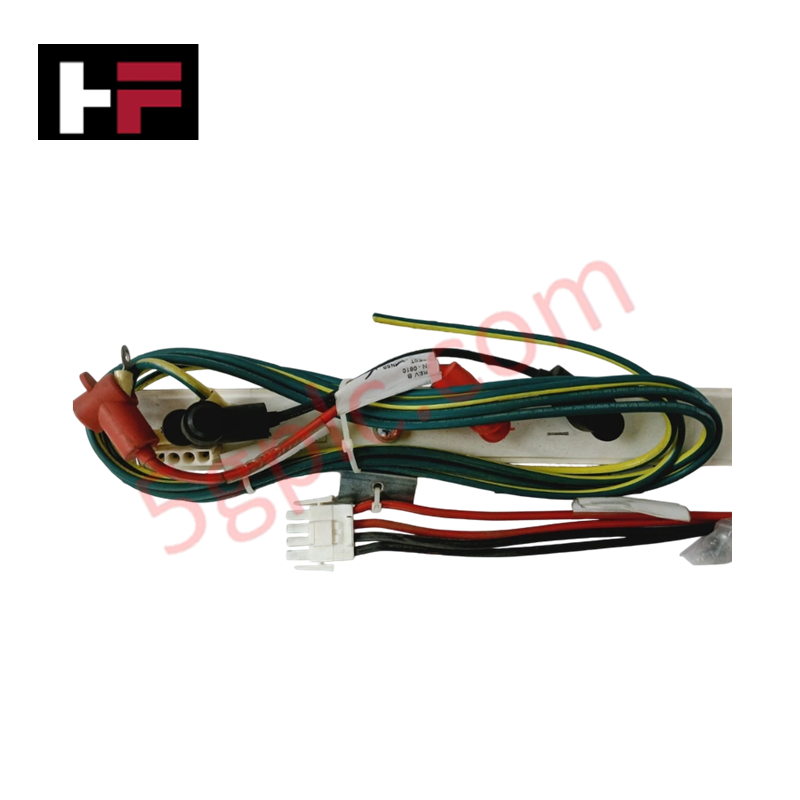
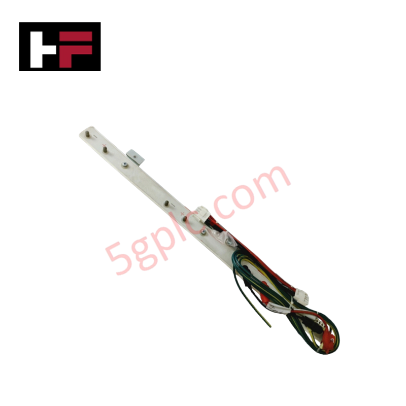
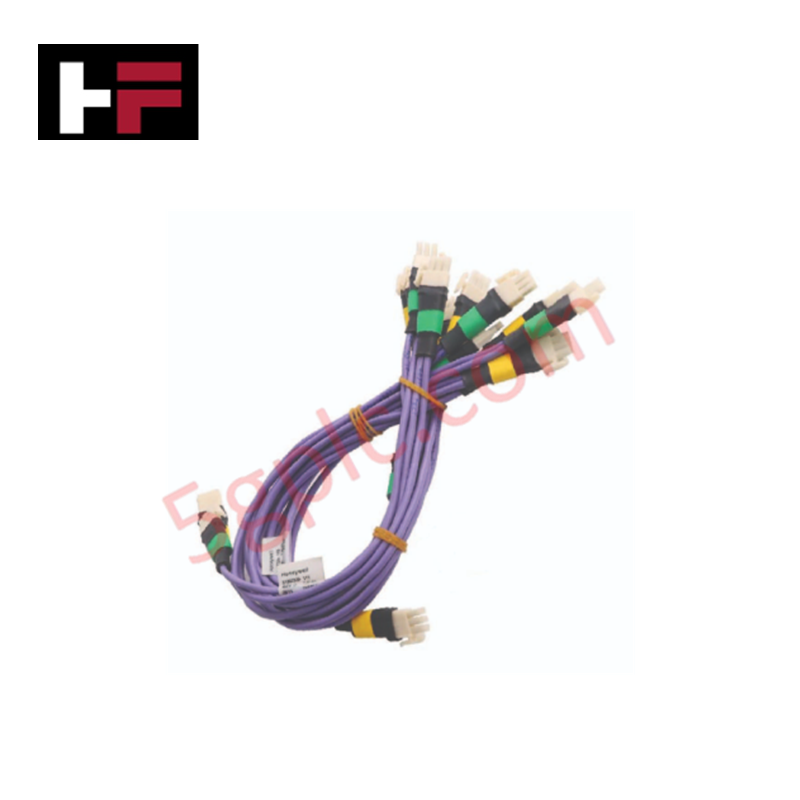
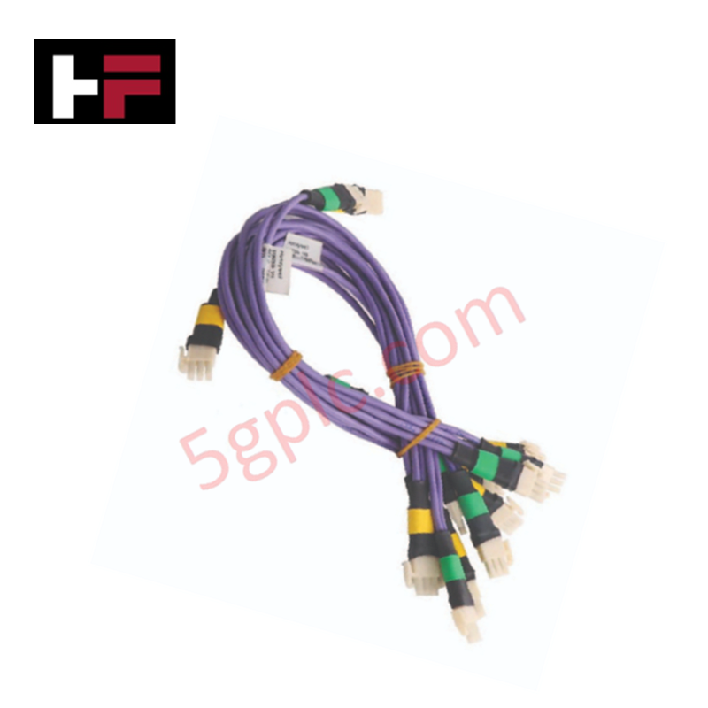
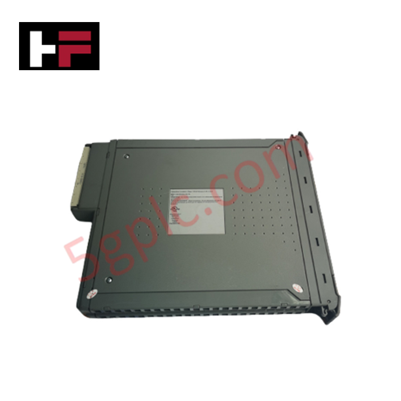
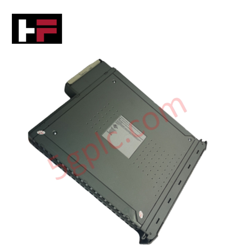
Configured for system-level fault isolation within Honeywell IPC and ISSC 600 control platforms, the Honeywell 621-0021 (621-0021 Diagnostic Module) provides direct electrical execution of diagnostic monitoring and signal status verification. The hardware serves as an integrated component for identifying process discrepancies and hardware malfunctions by analyzing AC and DC signal states across the control network.
Hardware Specifications
| Parameter | Specification |
|---|---|
| Model | 621-0021 |
| Brand | Honeywell |
| AC Output Rating | 1 A at 24 V, 500 mA at 115 V, 80 mA at 230 V |
| DC Output Rating | 1 A at 24 V |
4-20 mA HART and Channel Isolation Technicalities
The 621-0021 diagnostic architecture utilizes precise channel-to-channel isolation to monitor discrete feedback loops without introducing signal distortion or loading effects on primary control paths. By maintaining galvanic separation, the module ensures that diagnostic routines do not interfere with field-side process measurements or the deterministic timing of the backplane bus. The circuitry is calibrated to detect transient threshold deviations, allowing for the logging of signal noise or state-change anomalies before they escalate into systemic controller errors.
Frequently Asked Questions
Q: Can this diagnostic module be configured for automated fail-safe state execution?
A: The module is intended for monitoring and troubleshooting. While it identifies error states, it does not act as a primary safety-rated logic solver. Fail-safe state transitions must be managed by the host PLC or DCS logic.
Q: How does this module interface with the IPC/ISSC 600 backplane?
A: The module communicates status updates via the designated I/O bus interface. Proper firmware compatibility must be verified with the host controller to ensure that diagnostic data packets are correctly parsed during system scans.
Field Installation Guidelines
- System Integration: Ensure the host IPC or ISSC 600 controller is powered down before module insertion into the rack.
- Signal Wiring: Connect monitored loops to the module terminals. Ensure all wiring is shielded to minimize inductive coupling, which could result in false-positive diagnostic reports.
- Grounding: Terminate the module chassis ground to a common instrumentation earth. Ensure the ground impedance is below 1 Ohm to facilitate effective common-mode noise suppression.
- Validation: Post-installation, perform a diagnostic handshake via the engineering workstation to confirm that the module is correctly recognized on the system backplane and that all active channels are reporting expected idle states.
Additional Information
- 100% Genuine Parts: All products are original and authentic, ensuring reliable industrial performance.
- 30-Day Refund Guarantee: Return any in-stock item within 30 days in original, unopened packaging for a full refund (excluding shipping and fees).
- 12-Month Warranty: Covers defects in materials or workmanship; excludes misuse, normal wear, or unauthorized modifications.
- Worldwide Shipping: We ship via USPS, UPS, FedEx, and DHL. Delivery times vary by country and may be subject to customs or import fees.
- Support & Contact: Technical and warranty assistance is available anytime. Contact us here: Contact.
- Purchase Guidance: Check product specifications and compatibility carefully before ordering to ensure proper application.
Tech & Buying Guide

The Shift to Flexible IO Modules in Modern Industrial Automation
Traditional control systems rely on dedicated Input Output (IO) cards for industrial automation. Each conventional module processes a single signal type, such as Digital Input (DI), Digital Output (DO), Analog Input (AI), or Analog Output (AO). A standard 16-channel card accepts only one specific channel type across all ports. This inflexible hardware design often creates severe engineering bottlenecks during project execution. Engineers frequently must install entirely new cards to accommodate a single extra sensor. Consequently, late design changes increase control cabinet space requirements and drive up project costs.

DCS Commissioning Steps in Industrial Automation Projects
Commissioning a Distributed Control System (DCS) represents a crucial milestone when deploying modern process automation infrastructure. Field engineers must execute systematic verification steps to transition complex control hardware from static installation to dynamic plant control. Proper commissioning ensures that controllers, I/O modules, network switches, and HMI software operate in strict compliance with engineering design specifications before introducing live process fluids.

PLC and DCS Control System Spares Strategy: Engineering Guidelines
Modern factory automation relies on high-speed fiber optic backbones to link distributed control systems across noise-intensive industrial environments. Unlike copper wiring, optical fibers transmit data via light pulses, making them completely immune to electromagnetic interference (EMI). Field engineers must master optical cable joining and fusion splicing techniques to guarantee low-loss data transmission across critical Programmable Logic Controller (PLC) and Distributed Control System (DCS) nodes.