










Product Details
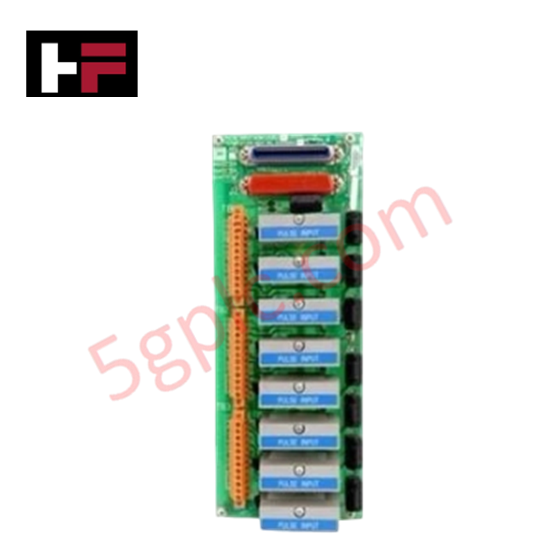
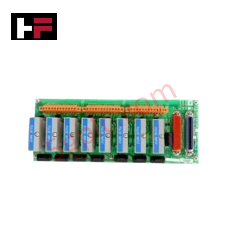
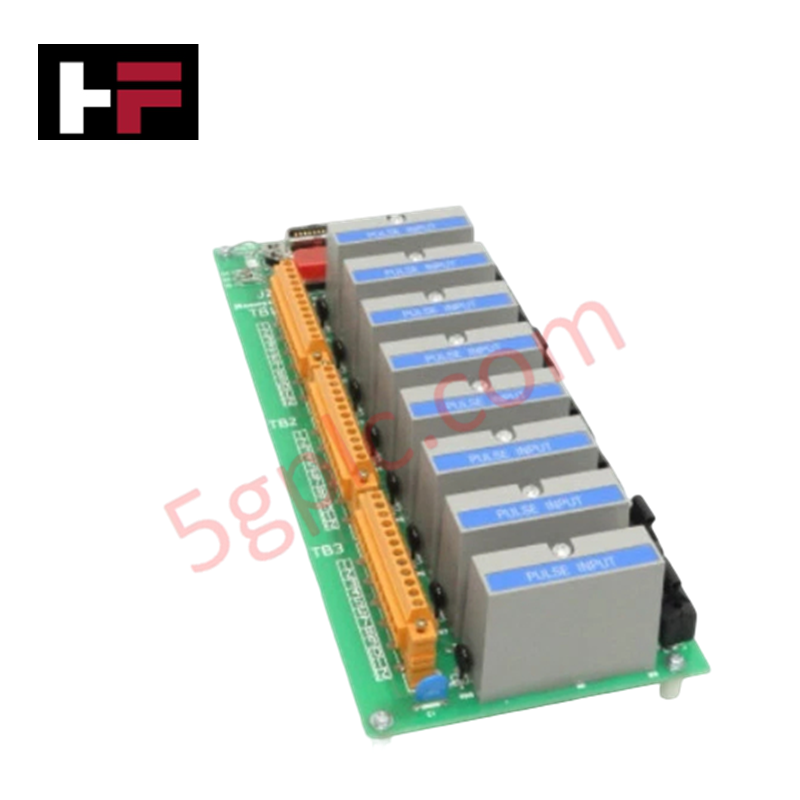
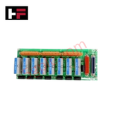
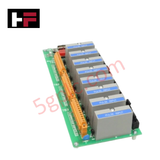
The Honeywell 51304084-175, also cataloged as the MC-TPIX12 Pulse Input Module, operates as a dedicated hardware component for high-speed pulse input processing within industrial automation control systems. Configured to interface directly with field pulse transmitters, the assembly captures frequency and counts across multiple independent channels, converting rapid voltage state transitions into internal digital data registers at high data transmission rates.
Hardware Specifications
| Parameter | Specification |
|---|---|
| Model | 51304084-175 MC-TPIX12 |
| Brand | Honeywell |
| Series / Module Type | PMIO / Pulse Input Module |
| Origin | United States |
| Weight | 0.7 kg |
| Dimensions | 30.8 cm x 12.1 cm x 7.2 cm |
| Operating Temp | -25 to +65 deg C |
| Power Consumption | Manufacturer standard backplane draw |
| Input Channels | 8 pulse inputs |
| Maximum Input Frequency | 10 kHz |
| Voltage Range | 0-30 VDC |
| Input Sensitivity | 0.5 V |
| Minimum Pulse Width | 10 us |
| Data Rate | 12 Mbps |
| Shock Resistance | 20 g |
| Vibration Resistance | 2 g (10-200 Hz) |
Channel-to-Channel Isolation and Pulse Processing
The Honeywell 51304084-175 features hardware-level electronic processing to evaluate input signals between 0-30 VDC with an input sensitivity threshold fixed at 0.5 V. The processing circuitry relies on integrated channel-to-channel isolation matrices to mitigate electromagnetic interference and eliminate common-mode voltage differences between isolated field instruments. Capable of handling a minimum pulse width of 10 us up to a maximum input frequency of 10 kHz, the input channels continuously filter high-frequency noise while the internal communication interface delivers processed metrics across the local bus at a synchronous 12 Mbps data rate.
Frequently Asked Questions
Q: What are the consequences if the input pulse width drops below the 10 us limit?
A: Pulses with a duration shorter than 10 us fall outside the detection threshold of the input filtering circuitry. This causes the internal counter to omit the transition event, resulting in registration losses and inaccurate totalization metrics inside the master controller.
Q: How does the module manage voltage transients on the 0-30 VDC field wiring lines?
A: Each channel on the MC-TPIX12 is equipped with physical overvoltage protection and channel-to-channel isolation networks. These sub-components clamp transient voltage spikes and restrict fault currents, protecting the internal 12 Mbps processing logic from destructive electrical surges.
Field Installation Guidelines
- DIN Rail Mounting: Secure the module chassis into the allocated carrier frame or standard 35 mm DIN rail structure. Ensure the top and bottom ventilation apertures are unobstructed to maintain passive convection airflow within the specified -25 to +65 deg C thermal operational envelope.
- Signal Terminal Wiring: Connect the pulse transmitter signal lines to the terminal blocks using twisted-pair conductors. Ensure insulation strip length does not exceed 10 mm to prevent accidental contact between neighboring channels.
- Shielding Protocols: Terminate the field instrument cable drain wire at the dedicated enclosure ground terminal point. The shield must be left ungrounded at the field sensor side to eliminate the generation of parasitic ground loops that alter the 0.5 V input sensitivity performance.
- Mechanical Lock Verification: Verify that the module's integrated structural retention mechanisms are fully latched before commissioning to guarantee electrical trace alignment across the interface backplane during 2 g vibration conditions.
Additional Information
- 100% Genuine Parts: All products are original and authentic, ensuring reliable industrial performance.
- 30-Day Refund Guarantee: Return any in-stock item within 30 days in original, unopened packaging for a full refund (excluding shipping and fees).
- 12-Month Warranty: Covers defects in materials or workmanship; excludes misuse, normal wear, or unauthorized modifications.
- Worldwide Shipping: We ship via USPS, UPS, FedEx, and DHL. Delivery times vary by country and may be subject to customs or import fees.
- Support & Contact: Technical and warranty assistance is available anytime. Contact us here: Contact.
- Purchase Guidance: Check product specifications and compatibility carefully before ordering to ensure proper application.




Tech & Buying Guide

Comprehensive Guide to PLC Types in Modern Industrial Automation
Modern industrial automation relies on programmable logic controllers to govern critical factory operations. System integrators classify PLCs based on scale, hardware architecture, and power supply design. Understanding these core categories enables automation engineers to select the right control system architecture. Consequently, proper hardware selection optimizes performance while minimizing long-term operational costs.

Demystifying the DDE Protocol in Legacy Industrial Automation Systems
Modern control systems rely heavily on seamless interprocess communication to exchange operational data between software programs. Microsoft first introduced the Dynamic Data Exchange (DDE) protocol in 1987 to enable real-time data sharing. In factory automation, DDE served as an early bridge between control software and Windows desktop applications. Therefore, understanding DDE mechanics provides crucial insights into how legacy industrial networks established software-level connectivity.

Demystifying CPU Communication Ports in Siemens PLC Architectures
Industrial automation relies heavily on robust data exchange between devices. Without seamless connectivity, field instruments, network switches, human-machine interfaces, and programmable logic controllers cannot coordinate effectively. Therefore, understanding the various CPU communication ports available in Siemens hardware ensures efficient factory automation design and seamless system integration.