










Product Details
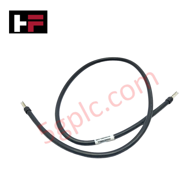
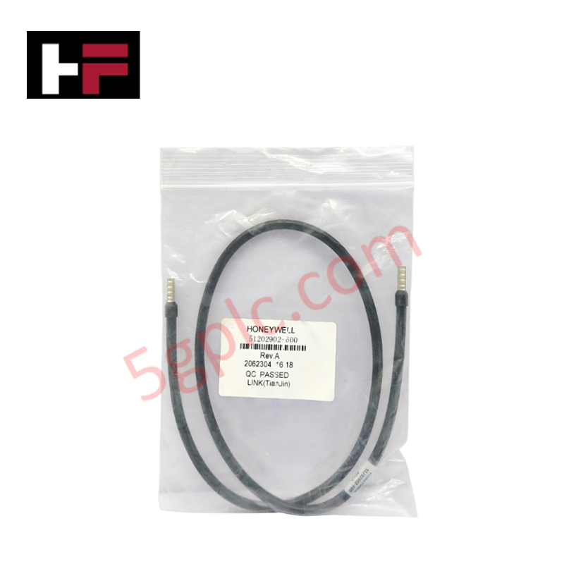
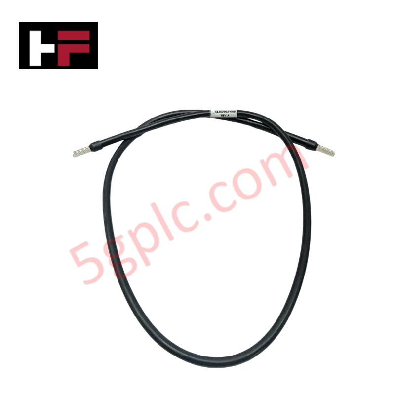
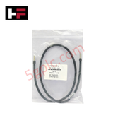
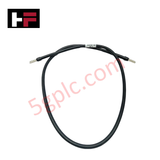
The Honeywell 51202902-600, also cataloged as the 51202902 Shielded Industrial Control Cable, operates as a dedicated hardware component for physical point-to-point signal interconnection within Experion PKS and C300 controller networks. The hardware establishes low-impedance electrical signal paths directly between processing nodes, I/O modules, and field termination assemblies to execute real-time control logic loop communication.
Hardware Specifications
| Parameter | Specification |
|---|---|
| Model | 51202902-600 |
| Brand | Honeywell |
| Origin | USA |
| Dimensions | 8.5 mm (Cable Diameter) |
| Operating Temp | -20 to +70 deg C |
| Power Consumption | Passive Component (Zero active electrical load) |
| Application | Signal transmission between C300 controller and FTAs |
| Cable Type | Shielded multi-conductor cable |
| Shielding | Dual-layer |
| Conductor Material | Stranded tinned copper |
| Insulation | Flame-retardant polyethylene |
| Outer Jacket | Heavy-duty PVC, UL 94V-0 flame rating |
| Operating Voltage | 300 V |
| Storage Temperature | -40 to +85 deg C |
Honeywell DCS Channel-to-Channel Isolation Parameters
The hardware assembly relies on its dual-layer shield and flame-retardant polyethylene dielectric insulation matrix to assist host modules in maintaining required channel-to-channel isolation limits. This architectural protection suppresses high-frequency inductive cross-talk and blocks transient common-mode voltage spikes across the high-density conductors, shielding vulnerable 4-20 mA HART loop protocol signal paths from external noise induction during industrial plant operations.
Frequently Asked Questions
Q: Can this industrial control cable be detached while the connected C300 controller or I/O loop is actively powered?
A: No, live removal can disrupt circuit boundaries and introduce inductive spikes; standard engineering operating protocol requires the related rack power supply to be isolated prior to hardware physical unlatching.
Q: How does the dual-layer shield structure impact network deployment in high-noise environments?
A: The dual-layer shield matrix forms a physical Faraday cage around the stranded tinned copper conductors, preventing radio frequency interference and electromagnetic noise from corrupting data transfers.
Field Installation Guidelines
- Route the 8.5 mm diameter shielded cable through low-voltage instrument raceways, keeping full physical separation from high-voltage AC cables or switching relay lines.
- Observe standard minimum bending radius parameters during installation to prevent mechanical elongation or structural tears in the internal dual-layer shield.
- Terminate the integrated cable shield drain wire directly to a single low-impedance copper instrument ground bar within the cabinet frame.
- Secure the heavy-duty PVC jacket inside the panel utilizing mechanical strain relief clamps to prevent terminal resistance shifts caused by continuous ambient plant vibration.
Additional Information
- 100% Genuine Parts: All products are original and authentic, ensuring reliable industrial performance.
- 30-Day Refund Guarantee: Return any in-stock item within 30 days in original, unopened packaging for a full refund (excluding shipping and fees).
- 12-Month Warranty: Covers defects in materials or workmanship; excludes misuse, normal wear, or unauthorized modifications.
- Worldwide Shipping: We ship via USPS, UPS, FedEx, and DHL. Delivery times vary by country and may be subject to customs or import fees.
- Support & Contact: Technical and warranty assistance is available anytime. Contact us here: Contact.
- Purchase Guidance: Check product specifications and compatibility carefully before ordering to ensure proper application.


Tech & Buying Guide

Demystifying the DDE Protocol in Legacy Industrial Automation Systems
Modern control systems rely heavily on seamless interprocess communication to exchange operational data between software programs. Microsoft first introduced the Dynamic Data Exchange (DDE) protocol in 1987 to enable real-time data sharing. In factory automation, DDE served as an early bridge between control software and Windows desktop applications. Therefore, understanding DDE mechanics provides crucial insights into how legacy industrial networks established software-level connectivity.

Demystifying CPU Communication Ports in Siemens PLC Architectures
Industrial automation relies heavily on robust data exchange between devices. Without seamless connectivity, field instruments, network switches, human-machine interfaces, and programmable logic controllers cannot coordinate effectively. Therefore, understanding the various CPU communication ports available in Siemens hardware ensures efficient factory automation design and seamless system integration.

Mastering the Siemens PLC Scan Cycle: How the CPU Executes Automation Programs
Industrial automation relies heavily on programmable logic controllers (PLCs) to manage complex manufacturing processes. Many engineers dive straight into programming without mastering the underlying architecture. However, understanding how a PLC CPU executes a program ensures reliable system design. Therefore, mastering the scan cycle optimizes both performance and troubleshooting in modern control systems.