











Product Details
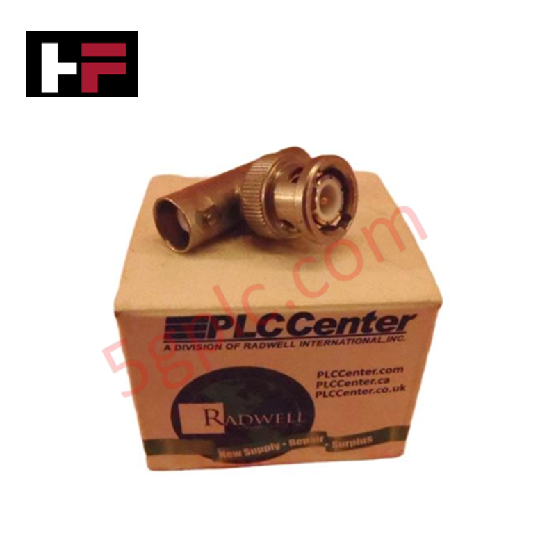
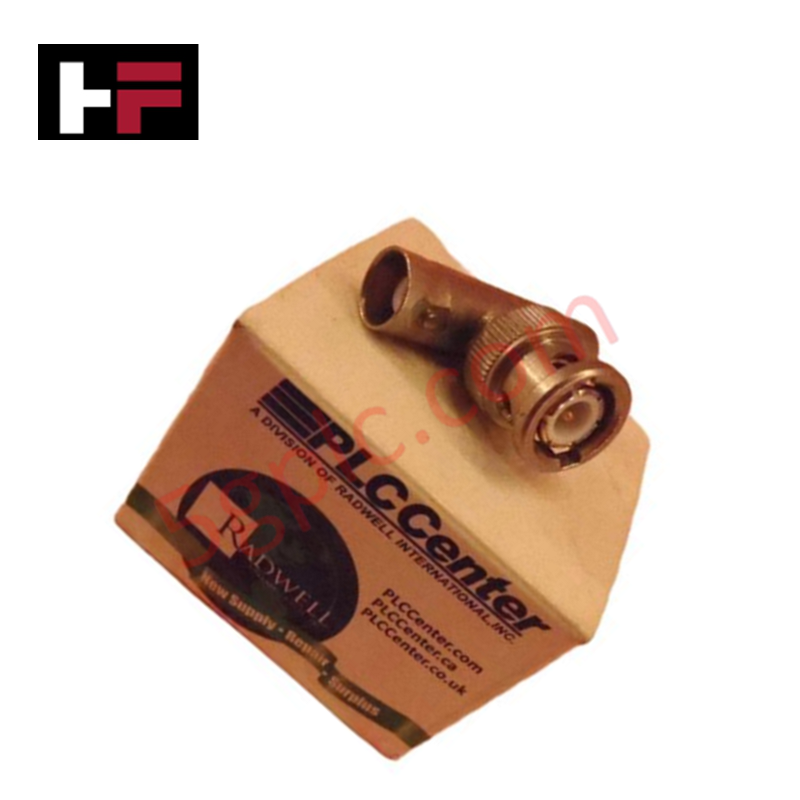
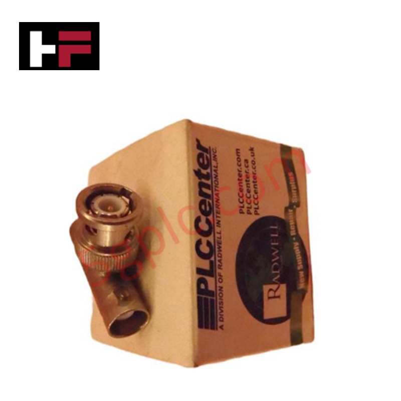
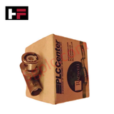
The Honeywell 51190728-105, also cataloged as the 51190728-105 BNC Tee Adapter, operates as a dedicated hardware component for coaxial bus branching and signal tap interconnections within Honeywell DCS networks. Constructed in a 1 x male plug to 2 x female jack configuration, the passive adapter splits or taps high-frequency serial communication and coaxial signal lines without altering transmission line characteristics. The metallic shell provides full 360-degree shield continuity across all three interface ports to suppress radio frequency interference and signal reflections.
Hardware Specifications
| Parameter | Specification |
|---|---|
| Model | 51190728-105 |
| Brand | Honeywell |
| Origin | USA |
| Weight | 0.03 lbs (0.014 kg) |
| Dimensions | Standard BNC Male-to-Dual-Female Profile |
| Operating Temp | -20 to 70 deg C |
| Power Consumption | Passive Component |
| Adapter Interface | 1 x BNC Male Plug to 2 x BNC Female Jacks |
| Nominal Impedance | 50/75 Ohm Coaxial Networks |
| Product Type | BNC Tee Adapter Connector |
| Body Material | Nickel-plated brass with gold-plated pin contacts |
Channel-to-Channel Isolation
The 51190728-105 maintains grounded conductive shielding across its 3-way junction to preserve channel-to-channel isolation between adjacent signal taps and external high-voltage field wiring. High-density metallic outer housing shields high-speed coaxial data transfers against external electromagnetic noise and cross-talk. When integrated into dual-redundant coaxial bus lines, the low-impedance grounding shell prevents stray voltage transients from degrading signal-to-noise ratios across field processing nodes.
Frequently Asked Questions
Q: Can the 51190728-105 BNC Tee Adapter be installed or removed while the coaxial network is actively transmitting data?
A: Disconnecting the adapter opens the coaxial transmission line, causing impedance mismatch, signal reflections, and potential node communication drops on that specific bus segment.
Q: What function does the male plug to dual female jack layout provide on a coaxial bus node?
A: The male connector attaches directly to the processor transceiver port, while the two female jacks allow in-and-out loop wiring of coaxial trunk cables with line termination resistors.
Q: How is chassis ground continuity maintained through the adapter?
A: The bayonet locking mechanism mechanically clamps the nickel-plated outer shell to the mating connector, establishing a low-resistance chassis ground path.
Field Installation Guidelines
- Inspect male and female BNC bayonet pins, dielectric insulators, and center contacts for corrosion or physical deformation prior to mounting.
- Align the bayonet slots of the 51190728-105 male plug with the receptacle lugs on the node card faceplate and push firmly while twisting to lock.
- Connect incoming and outgoing coaxial cables to the two female BNC jacks, ensuring both bayonet locks fully snap into position.
- Verify that bus termination resistors (50 Ohm or 75 Ohm as specified by network architecture) are fitted to open female ports at the physical ends of the cable run.
- Avoid applying excessive side-loading mechanical stress to the adapter body when routing rigid coaxial cables through cabinet wireways.
Additional Information
- 100% Genuine Parts: All products are original and authentic, ensuring reliable industrial performance.
- 30-Day Refund Guarantee: Return any in-stock item within 30 days in original, unopened packaging for a full refund (excluding shipping and fees).
- 12-Month Warranty: Covers defects in materials or workmanship; excludes misuse, normal wear, or unauthorized modifications.
- Worldwide Shipping: We ship via USPS, UPS, FedEx, and DHL. Delivery times vary by country and may be subject to customs or import fees.
- Support & Contact: Technical and warranty assistance is available anytime. Contact us here: Contact.
- Purchase Guidance: Check product specifications and compatibility carefully before ordering to ensure proper application.



Tech & Buying Guide

DCS Commissioning Steps in Industrial Automation Projects
Commissioning a Distributed Control System (DCS) represents a crucial milestone when deploying modern process automation infrastructure. Field engineers must execute systematic verification steps to transition complex control hardware from static installation to dynamic plant control. Proper commissioning ensures that controllers, I/O modules, network switches, and HMI software operate in strict compliance with engineering design specifications before introducing live process fluids.

PLC and DCS Control System Spares Strategy: Engineering Guidelines
Modern factory automation relies on high-speed fiber optic backbones to link distributed control systems across noise-intensive industrial environments. Unlike copper wiring, optical fibers transmit data via light pulses, making them completely immune to electromagnetic interference (EMI). Field engineers must master optical cable joining and fusion splicing techniques to guarantee low-loss data transmission across critical Programmable Logic Controller (PLC) and Distributed Control System (DCS) nodes.

PLC and DCS Control System Spares Strategy: Engineering Guidelines
Industrial automation lifecycle management requires robust spare parts planning for Programmable Logic Controller (PLC) and Distributed Control System (DCS) platforms. Plant engineers must correctly categorize spare components during front-end engineering design to maintain high system availability. Miscalculating spare requirements can lead to prolonged unscheduled downtime, project budget overruns, or delayed site commissioning.