


Product Details
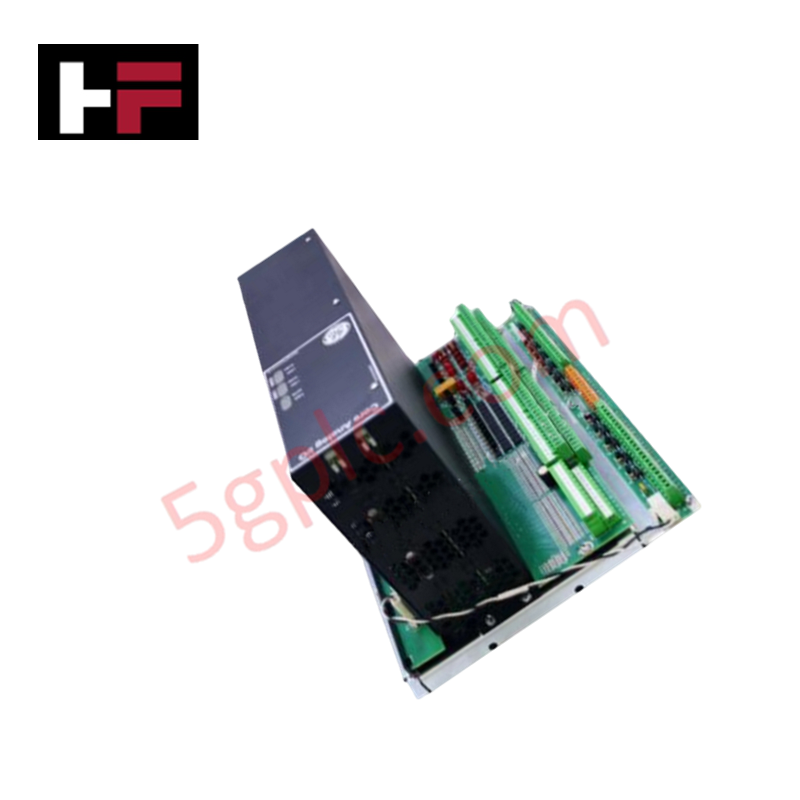
Configured for high-density signal acquisition and control in Mark VIe gas turbine platforms, the GE IS230PCAAH1A (IS230PCAAH1A Core Analog Module) provides direct physical/electrical execution. This module handles a comprehensive array of I/O types, including thermocouple inputs, 4-20 mA current loops, seismic vibration monitoring, LVDT excitation, pulse rate inputs, and servo coil outputs.
Hardware Specifications
| Parameter | Specification |
|---|---|
| Model | IS230PCAAH1A |
| Brand | General Electric |
| Origin | USA |
| Weight | Not specified |
| Dimensions | 17.71 cm x 13.77 cm x 7.87 cm |
| Operating Temp | -30 to 65 deg C |
| Power Consumption | 28 VDC nominal |
Profinet / EtherNet/IP Deterministic Networks
The IS230PCAAH1A module relies on precise backplane bus communication velocity to maintain deterministic control loops across simplex, dual, and TMR architectures. System performance is tied to firmware flash compatibility between the PCAA module and the host controller, ensuring synchronized data exchange over the dual RJ45 Ethernet ports. I/O density scaling is achieved through modular integration with the TCAT terminal board; when operating in TMR modes, signal fan-out must be managed via the TCAT to ensure data consistency across redundant PCAA modules. Users must adhere to defined timing constraints to prevent bus congestion during high-frequency LVDT and servo feedback polling.
Frequently Asked Questions
Q: Is the IS230PCAAH1A field-repairable at the component level?
A: No. The PCAA module is considered a single least replaceable unit (LRU). Internal board-level diagnosis or repair is not supported; faulty units must be replaced as an entire assembly.
Q: Can the PCAA module operate without the TCAT terminal board?
A: Yes. The PCAA module can function independently for dedicated I/O tasks. However, TCAT is required if fanned signal inputs are necessary for dual or TMR redundant configurations.
Field Installation Guidelines
- Interface Connections: Connect the PCAA module to the TCAT terminal board using the two provided 68-pin cables (connectors P1 and P2). Verify that these cables are fully seated and secured to prevent intermittent signal integrity issues.
- Power and Network: Provide 28 VDC power to the module's dedicated connector and establish network connectivity via the dual RJ45 Ethernet ports. Ensure auxiliary 24 V field power and shield grounding are supplemented by the adjacent JGPA board as required.
- Wiring Termination: Field device I/O should be landed on the 120 Euro-style box terminals located on the module edge. Ensure proper wire stripping and torque application to prevent terminal oxidation or loosening due to turbine vibration.
- Grounding: Ensure the module chassis is bonded to the control cabinet ground bus to provide a low-impedance reference for analog signals. Route sensitive signal wiring (thermocouples, LVDT) through shielded conduit, separated from high-current AC power cables to prevent electromagnetic crosstalk.
Additional Information
- 100% Genuine Parts: All products are original and authentic, ensuring reliable industrial performance.
- 30-Day Refund Guarantee: Return any in-stock item within 30 days in original, unopened packaging for a full refund (excluding shipping and fees).
- 12-Month Warranty: Covers defects in materials or workmanship; excludes misuse, normal wear, or unauthorized modifications.
- Worldwide Shipping: We ship via USPS, UPS, FedEx, and DHL. Delivery times vary by country and may be subject to customs or import fees.
- Support & Contact: Technical and warranty assistance is available anytime. Contact us here: Contact.
- Purchase Guidance: Check product specifications and compatibility carefully before ordering to ensure proper application.


Tech & Buying Guide

Essential Motion Control Commands: A Practical Guide for Engineers
Automation engineers often rely on precise position and speed control to drive modern factory machinery. Modern industrial systems, such as Programmable Logic Controllers (PLCs) and Distributed Control Systems (DCS), depend heavily on standardized motion instructions. Mastering these commands ensures operational safety, protects mechanical components, and optimizes cycle times across production lines.

The Role of Intrinsic Safety Barriers in PLC and DCS Architectures
Implementing robust protection in hazardous industrial environments represents a fundamental safety requirement in factory automation. Process facilities often handle volatile gases, dusts, and chemical agents that pose significant combustion risks. Consequently, control system engineers must deploy energy-limiting interfaces to isolate safe-area control cabinets from hazardous-area field instrumentation. This article examines the function, selection, and electrical principles of intrinsic safety barriers within modern PLC and DCS networks.

Architectural Selection and Scale Classification of PLC Systems in Industrial Automation
Selecting the correct control platform represents a foundational engineering decision in factory automation. System designers must carefully balance technical parameters against long-term operational requirements when implementing a Programmable Logic Controller (PLC). This article examines the critical evaluation metrics, physical scale classifications, and operational architectures of modern control systems.