


Product Details
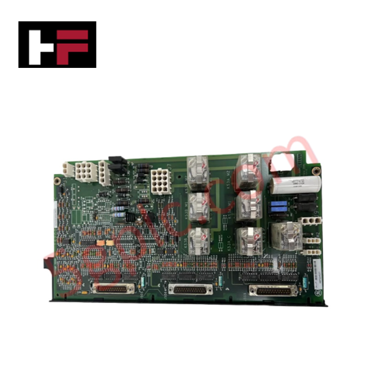
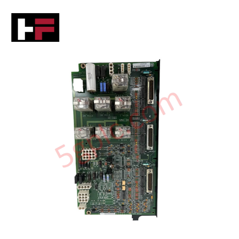
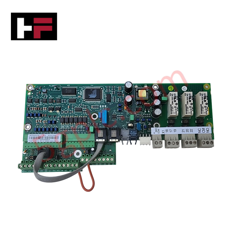
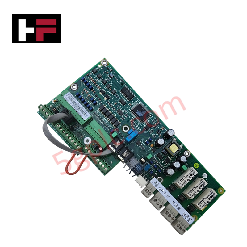
Configured for high-speed switching operations in EX2100 excitation control systems, the GE IS200EXHSG3AEC (IS200EXHSG3AEC Exciter HS Relay Driver Board) provides direct physical/electrical execution of contactor and relay drive control.
Hardware Specifications
| Parameter | Specification |
|---|---|
| Model | IS200EXHSG3AEC |
| Brand | General Electric |
| Origin | USA |
| Dimensions | 8.26 cm x 4.19 cm x 12.1 cm |
| Relay Channels | 12 |
| Technology | Surface-mount |
Profinet / EtherNet/IP Deterministic Networks
The IS200EXHSG3AEC operates as an output interface node within the EX2100 architecture, managing the high-speed actuation of DC contactors and pilot relays. The module processes field-flashing signals (53A/53B) and de-excitation status (KDEP) with deterministic timing, ensuring that control transitions are synchronized with the system's excitation requirements. Through its integration with the Excitation Monitoring and Instrumentation Output (EMIO) system, the board conditions status signals from the Exciter De-Excitation Board (EDEX) and crowbar circuits. Firmware flash compatibility is managed via the controller backplane, allowing for precise adjustment of relay drive parameters and I/O density scaling during system configuration.
Frequently Asked Questions
Q: Can the IS200EXHSG3AEC be hot-swapped during excitation system operation?
A: No. Removing or inserting the module while the excitation system is energized will interrupt the drive signals for field flashing and de-excitation relays, leading to a system trip or loss of excitation control.
Q: How does the board handle signal feedback from external de-excitation boards?
A: The board performs hardware-level signal conditioning on inputs received from the EDEX and EXDE boards. These conditioned signals are then routed through the EMIO system for monitoring and safety verification.
Field Installation Guidelines
- Mounting: Ensure the board is firmly secured within the EX2100 cabinet slot. Use the designated retention clips to maintain electrical continuity with the backplane connectors.
- Wiring Integrity: Use shielded cabling for all feedback signals originating from the EDEX or EXDE boards to prevent electromagnetic interference from degrading status signal accuracy.
- Relay Circuit Protection: Ensure that the DC contactor coils driven by the onboard relays are protected with flyback diodes or appropriate transient suppression devices to prevent voltage spikes that could damage the surface-mount drive circuitry.
- Connector Inspection: Periodically verify that all D-type and edge connectors are free of oxidation and debris. Poor contact impedance can lead to delayed relay response times or intermittent driver failures.
Additional Information
- 100% Genuine Parts: All products are original and authentic, ensuring reliable industrial performance.
- 30-Day Refund Guarantee: Return any in-stock item within 30 days in original, unopened packaging for a full refund (excluding shipping and fees).
- 12-Month Warranty: Covers defects in materials or workmanship; excludes misuse, normal wear, or unauthorized modifications.
- Worldwide Shipping: We ship via USPS, UPS, FedEx, and DHL. Delivery times vary by country and may be subject to customs or import fees.
- Support & Contact: Technical and warranty assistance is available anytime. Contact us here: Contact.
- Purchase Guidance: Check product specifications and compatibility carefully before ordering to ensure proper application.

Tech & Buying Guide

Essential Motion Control Commands: A Practical Guide for Engineers
Automation engineers often rely on precise position and speed control to drive modern factory machinery. Modern industrial systems, such as Programmable Logic Controllers (PLCs) and Distributed Control Systems (DCS), depend heavily on standardized motion instructions. Mastering these commands ensures operational safety, protects mechanical components, and optimizes cycle times across production lines.

The Role of Intrinsic Safety Barriers in PLC and DCS Architectures
Implementing robust protection in hazardous industrial environments represents a fundamental safety requirement in factory automation. Process facilities often handle volatile gases, dusts, and chemical agents that pose significant combustion risks. Consequently, control system engineers must deploy energy-limiting interfaces to isolate safe-area control cabinets from hazardous-area field instrumentation. This article examines the function, selection, and electrical principles of intrinsic safety barriers within modern PLC and DCS networks.

Architectural Selection and Scale Classification of PLC Systems in Industrial Automation
Selecting the correct control platform represents a foundational engineering decision in factory automation. System designers must carefully balance technical parameters against long-term operational requirements when implementing a Programmable Logic Controller (PLC). This article examines the critical evaluation metrics, physical scale classifications, and operational architectures of modern control systems.