


Product Details
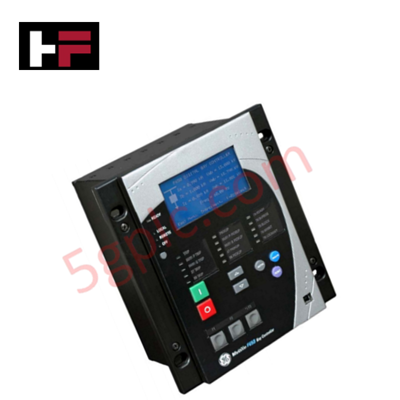
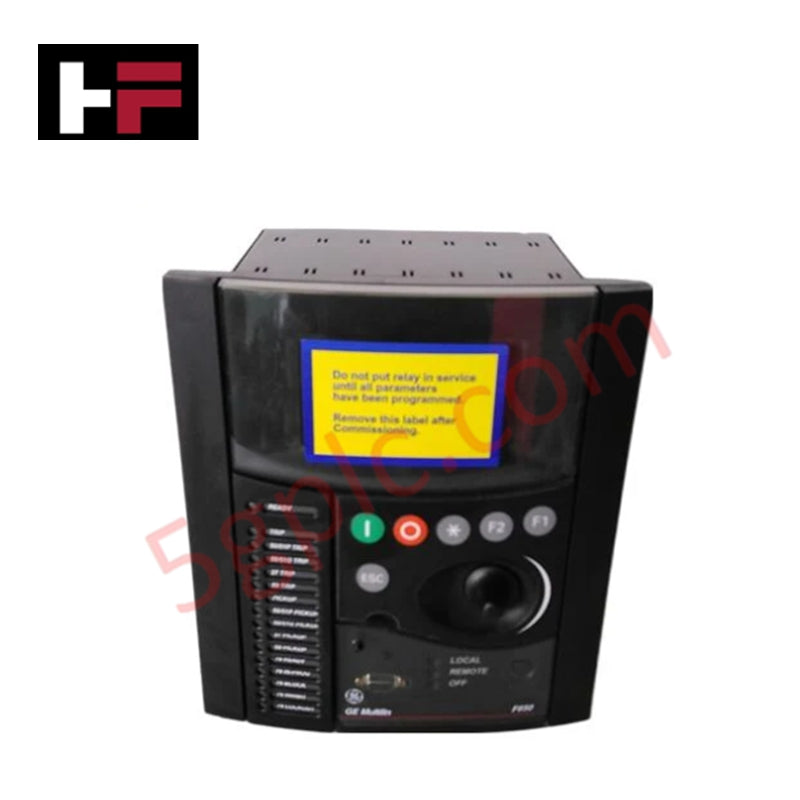
Configured for bay control and protection in electrical distribution systems, the GE Multilin F650BABF1G0HI (F650 Digital Bay Controller) provides direct physical/electrical execution of logic-based switching and communication management for substation automation platforms.
Suffix Breakdown & Model Matrix
- F650: Base series for numerical feeder and bay management.
- B: Basic display module configuration.
- A: Rear redundant RS485 serial communication board.
- B: Rear 10/100 Base TX Ethernet communication board.
- F1: Slot F populated with 16 digital inputs and 8 digital outputs.
- G0: Slot G configuration (No I/O expansion).
- HI: Auxiliary power supply range (88-300 VDC or 96-250 VAC).
Hardware Specifications
| Parameter | Specification |
|---|---|
| Model | F650BABF1G0HI |
| Brand | GE Multilin |
| Weight | 5 kg |
| Operating Temp | Standard industrial ambient |
| Power Consumption | 88-300 VDC / 96-250 VAC |
| Digital I/O | 16 Inputs, 8 Outputs |
| Protocols | Modbus RTU, TCP/IP, DNP 3.0, IEC 60870-5-104 |
Deterministic Industrial Control Networks
The F650 integrates into high-speed substation LANs, requiring precise configuration of backplane bus communication velocity to maintain real-time telemetry. The module supports I/O density scaling via slot-specific expansion boards; ensure that firmware flash compatibility matches the master station's control logic requirements. Deterministic behavior is maintained through standard protocol stacks (IEC 60870-5-104, DNP 3.0), which facilitate time-stamped event reporting. Integration engineers must verify that the Ethernet and RS485 communication ports are isolated from high-voltage transients using appropriate surge suppression techniques to avoid packet latency or bus collisions.
Frequently Asked Questions
Q: Can the F650 be hot-swapped during active bay monitoring?
A: No. The unit must be fully isolated from control power and primary inputs before removal. Hot-swapping will result in a loss of protection and potential corruption of the non-volatile memory registers.
Q: How is the F650 configured for redundant communication?
A: The redundant RS485 port configuration (Suffix A) allows for dual-path serial communication. Ensure that both physical paths are correctly terminated according to the EIA-485 standard to prevent signal reflections that cause intermittent link drops.
Field Installation Guidelines
- Mounting: Secure the controller in a standard rack using the provided mounting hardware. Ensure the chassis is bonded to the substation earth-ground bus using a copper strap to meet electromagnetic compatibility requirements.
- Auxiliary Power Wiring: Connect the auxiliary power source (88-300 VDC or 96-250 VAC) to the dedicated power terminal blocks. Maintain physical separation between power leads and signal wiring to avoid inductive coupling.
- I/O Shielding: Route digital input and output cables through dedicated conduits. Use shielded cabling for all external I/O points, terminating the shields only at the relay-end ground point to prevent ground loops.
- Communications: Verify that Ethernet (10/100 Base TX) cables comply with CAT5e or higher standards. Ensure the RJ45 and RS485 connectors are fully seated and free from mechanical tension.
Additional Information
- 100% Genuine Parts: All products are original and authentic, ensuring reliable industrial performance.
- 30-Day Refund Guarantee: Return any in-stock item within 30 days in original, unopened packaging for a full refund (excluding shipping and fees).
- 12-Month Warranty: Covers defects in materials or workmanship; excludes misuse, normal wear, or unauthorized modifications.
- Worldwide Shipping: We ship via USPS, UPS, FedEx, and DHL. Delivery times vary by country and may be subject to customs or import fees.
- Support & Contact: Technical and warranty assistance is available anytime. Contact us here: Contact.
- Purchase Guidance: Check product specifications and compatibility carefully before ordering to ensure proper application.


Tech & Buying Guide

Essential SCADA Features for Modern IoT-Enabled Industrial Automation
The convergence of traditional SCADA systems with the Industrial Internet of Things (IIoT) has redefined factory automation. Choosing a robust platform requires more than just standard monitoring capabilities. In this era of Industry 4.0, your supervisory system must bridge the gap between legacy control systems and enterprise-level data integration.

Selecting Rockwell Automation Allen-Bradley PLCs for Small and Mid-Sized Applications
Rockwell Automation remains a cornerstone in global industrial automation. Their Allen-Bradley brand provides a comprehensive portfolio of control systems designed to meet diverse production requirements. Choosing the right programmable logic controller (PLC) is critical for system reliability and scalability. This guide analyzes the Micro and Compact Logix families to help you select the optimal solution for small and medium-scale projects.

Strategic Selection: Choosing the Right SCADA Software for Your PLC Project
In industrial automation, the SCADA (Supervisory Control and Data Acquisition) system acts as the bridge between raw machine data and actionable human intelligence. Selecting the incorrect software platform can lead to integration bottlenecks, scalability issues, and excessive long-term maintenance costs. As an automation consultant with 15 years of experience, I have guided many projects through the selection process. Below are the essential criteria for choosing a platform that ensures both performance and longevity.