


Product Details
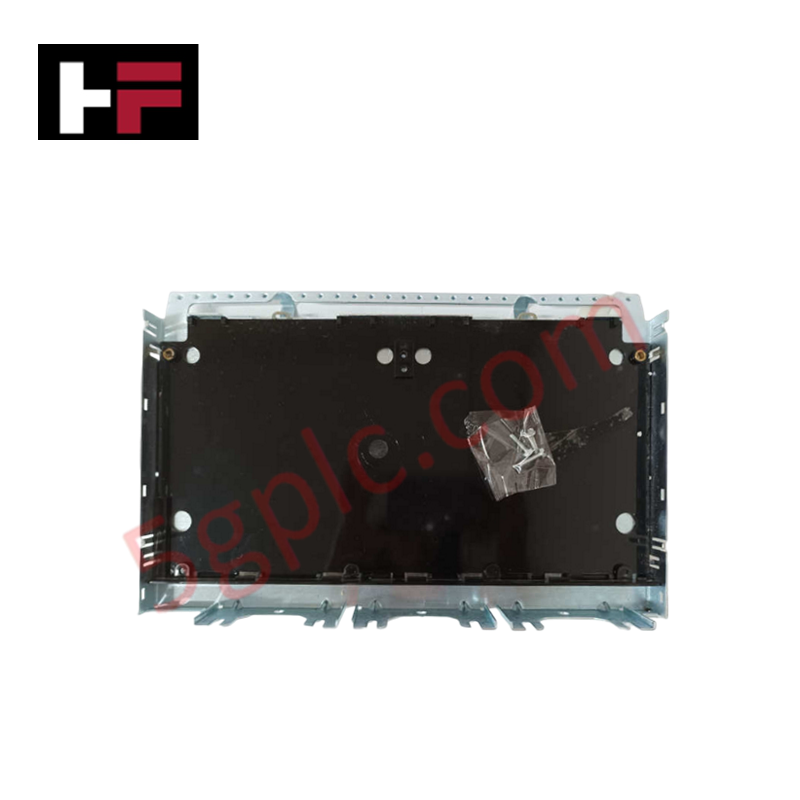
The GE IS230TDBTH6A, also cataloged as the IS230TDBTH6A Discrete I/O Board, operates as a dedicated hardware component for TMR contact input and relay output execution within Mark VIe control platforms. Configured for high-density signal handling, this terminal board provides direct physical execution of twenty-four isolated contact inputs and twelve form-C relay outputs.
Hardware Specifications
| Parameter | Specification |
|---|---|
| Model | IS230TDBTH6A |
| Brand | GE |
| Origin | USA |
| Weight | Not specified |
| Dimensions | 17.8 cm wide x 33.02 cm high |
| Operating Temp | -30 deg C to 65 deg C |
| Power Consumption | System-dependent |
| Core Performance | 24 contact inputs; 12 form-C relay outputs |
Industrial Control and I/O Density Scaling
The IS230TDBTH6A facilitates I/O density scaling through a triple modular redundancy (TMR) architecture requiring three PDIO I/O packs. Each contact input features integrated hardware filtering (4 ms) and noise suppression circuitry to mitigate surge and high-frequency interference. The board supports field-selectable wetting voltages of 24 VDC, 48 VDC, or 125 VDC. Communication with the R, S, and T controllers is established via three dedicated D-type connectors (JR1, JS1, JT1), enabling redundant Ethernet networking to each associated PDIO pack. Firmware flash compatibility and deterministic data exchange are managed by the PDIO packs, which require all three modules to be present for correct TMR operation; single I/O pack deployment is not supported by the TDBT hardware configuration.
Frequently Asked Questions
Q: Can the IS230TDBTH6A be operated with a single PDIO I/O pack?
A: No. The TDBT board is engineered specifically for TMR redundancy. Attempting to run the system with a single I/O pack will result in incomplete logic voting and system-level communication faults.
Q: How are the contact inputs protected against electrical noise?
A: The contact inputs are equipped with onboard hardware filters and noise suppression components designed to reject high-frequency interference and voltage surges from field wiring.
Field Installation Guidelines
- Mounting: The board supports both DIN-rail mounting and flat-surface installation. Ensure the mounting orientation allows for adequate clearance of the three PDIO I/O pack connections.
- Wiring: Connect external contact inputs to the board while ensuring the wetting voltage matches the specified nominal input range (24/48/125 VDC). Use shielded cabling for input circuits to maintain noise immunity.
- Grounding: Establish a robust ground connection between the board chassis and the cabinet ground bus to ensure the efficacy of the surge protection circuitry.
- Connectivity: Verify the correct mapping of D-type connectors to the corresponding controller networks (JR1 to R, JS1 to S, JT1 to T) to maintain the integrity of the TMR voting architecture.
Additional Information
- 100% Genuine Parts: All products are original and authentic, ensuring reliable industrial performance.
- 30-Day Refund Guarantee: Return any in-stock item within 30 days in original, unopened packaging for a full refund (excluding shipping and fees).
- 12-Month Warranty: Covers defects in materials or workmanship; excludes misuse, normal wear, or unauthorized modifications.
- Worldwide Shipping: We ship via USPS, UPS, FedEx, and DHL. Delivery times vary by country and may be subject to customs or import fees.
- Support & Contact: Technical and warranty assistance is available anytime. Contact us here: Contact.
- Purchase Guidance: Check product specifications and compatibility carefully before ordering to ensure proper application.


Tech & Buying Guide

Why 24V DC Power Supplies Standardize Modern Industrial Automation
Industrial control cabinets worldwide rely on 24V DC as the universal power standard for field instrumentation, sensors, and controllers. Walk into any manufacturing plant, and you will find PLCs, human-machine interfaces (HMIs), and smart actuators running on extra-low voltage DC. Standardizing on 24V DC enhances operational safety, lowers cabinet footprint, and maintains steady control performance across factory networks.

Essential Motion Control Commands: A Practical Guide for Engineers
Automation engineers often rely on precise position and speed control to drive modern factory machinery. Modern industrial systems, such as Programmable Logic Controllers (PLCs) and Distributed Control Systems (DCS), depend heavily on standardized motion instructions. Mastering these commands ensures operational safety, protects mechanical components, and optimizes cycle times across production lines.

Mastering Modern Industrial Joystick Controls in Heavy Automation
Industrial joysticks play a pivotal role in human-machine interaction across heavy material handling and mobile hydraulics. These tactile controllers translate complex operator movements into precise electrical signals for PLCs, motion controllers, and DCS networks. Consequently, selecting and installing the right joystick architecture ensures operator safety, reduces fatigue, and optimizes equipment performance.