










Product Details
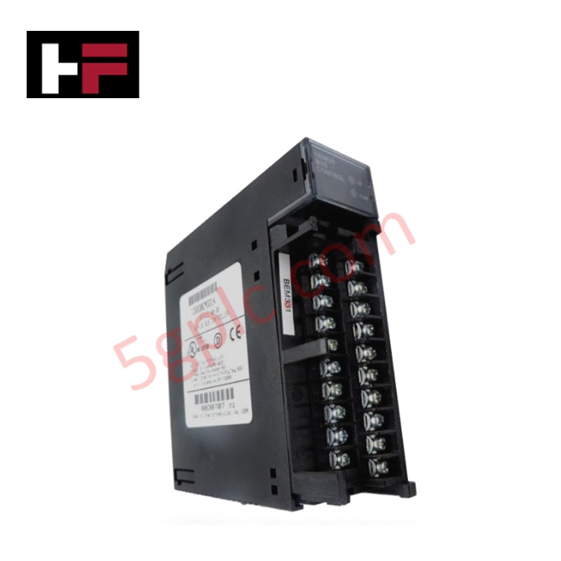
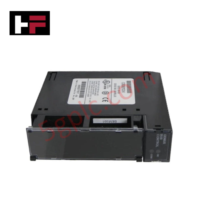
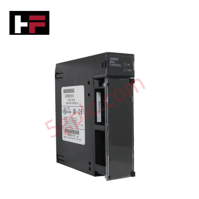
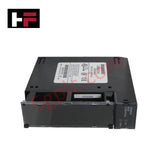
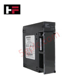
The GE Fanuc IC693BEM331K, also cataloged as the IC693BEM331 Genius Bus Controller, operates as a dedicated hardware component for serial bus communication execution between the Series 90-30 PLC backplane and Genius I/O field networks.
Hardware Specifications
| Parameter | Specification |
|---|---|
| Model | IC693BEM331K |
| Brand | GE Fanuc |
| Origin | USA |
| Weight | 0.38 kg (0.84 lbs) |
| Dimensions | Single-slot Series 90-30 format |
| Operating Temp | 0 to 60 deg C |
| Power Consumption | 1.5 W (300 mA at 5 VDC) |
| Product Line | Series 90-30 |
| Device Capacity | Up to 31 devices on Genius I/O bus |
| Maximum Data Payload | Up to 128 bytes send/receive control data |
| Backplane Draw | 300 mA from 5 VDC bus |
| Network Protocol | Genius I/O serial bus / Global Data |
| Hardware Compatibility | Series 90-30 PLC racks, Genius Blocks, Field Control BIU |
Backplane Bus Communication & Firmware Integration
The module negotiates control data transfer across the local Series 90-30 backplane bus to ensure predictable communication velocity between CPU sweep cycles and remote Genius nodes. The board logic converts high-density backplane I/O traffic into serial datagrams, coordinating up to 128 bytes of input and output transfer sequences across 31 Genius I/O bus addresses.
I/O density scaling allows integration with Genius discrete blocks, analog blocks, and Field Control I/O stations equipped with Bus Interface Units (BIU). Firmware flash compatibility ensures persistent configuration storage for I/O scanning modes, enhanced diagnostic commands, and Global Data broadcast routines without requiring onboard battery retention.
Frequently Asked Questions
Q: How is physical line verification managed on the Genius bus without relying on 90-70 style fault table counts?
A: Verification of configuration integrity is executed by evaluating the GBC Device Present status bit within the PLC application logic, rather than relying on fault table configuration error counts.
Q: What are the backplane power supply draw limits for the module when installed in a Series 90-30 chassis?
A: The module draws 300 mA from the +5 VDC supply rail provided through the Series 90-30 baseplate backplane connector during standard operation.
Q: Can the module be inserted or removed while the Series 90-30 rack is powered on?
A: No. System power to the baseplate rack must be disconnected before installing or extracting the module to prevent damage to the backplane edge connectors and logical disruptions on the active bus.
Field Installation Guidelines
- Power Shutdown: Turn off all primary AC/DC system power supplying the Series 90-30 baseplate before inserting the module into its designated slot.
- Backplane Insertion: Align the rear circuit card edges with the plastic card guides of the selected chassis slot. Slide the card backward until the backplane connector locks firmly into place.
- Serial Bus Wiring: Connect the shielded twisted-pair Genius serial bus cable to the front terminal assembly. Ensure proper daisy-chain topology across all 31 potential device drops on the line.
- Shield Grounding: Terminate the cable shield drain wire directly to the chassis ground terminal to maintain signal integrity and prevent noise coupling on serial differential lines.
- Bus Line Termination: Install standard 75-ohm or 100-ohm line terminating resistors across the physical serial tap terminals at the two physical ends of the Genius network trunk.
Additional Information
- 100% Genuine Parts: All products are original and authentic, ensuring reliable industrial performance.
- 30-Day Refund Guarantee: Return any in-stock item within 30 days in original, unopened packaging for a full refund (excluding shipping and fees).
- 12-Month Warranty: Covers defects in materials or workmanship; excludes misuse, normal wear, or unauthorized modifications.
- Worldwide Shipping: We ship via USPS, UPS, FedEx, and DHL. Delivery times vary by country and may be subject to customs or import fees.
- Support & Contact: Technical and warranty assistance is available anytime. Contact us here: Contact.
- Purchase Guidance: Check product specifications and compatibility carefully before ordering to ensure proper application.




Tech & Buying Guide
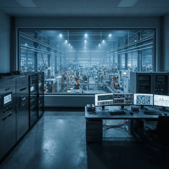
Understanding Modern SCADA Systems: Architecture, Communication Topologies, and Industrial Applications
Supervisory Control and Data Acquisition (SCADA) systems form the digital backbone of modern industrial automation. They collect critical field data, transmit signals across vast distances, and empower plant operators with real-time process visibility. Across modern infrastructures, SCADA solutions streamline centralized control and maintain continuous operational uptime.

Understanding OPC Servers in Modern Industrial Automation: Principles, Architecture, and Applications
In industrial automation, connecting physical hardware with high-level software remains a primary operational challenge. Factories utilize programmable logic controllers (PLCs), distributed control systems (DCS), human-machine interfaces (HMIs), and smart sensors from diverse vendors. These devices often speak different proprietary protocols. Open Platform Communications (OPC) servers solve this interoperability challenge by standardizing how data flows across factory networks.

Industrial Fiber Optic Cables: Principles, Connectors, and Fusion Splicing Techniques
Modern factory automation relies heavily on fiber optic cables for high-speed industrial data transmission. Fiber optic cables transmit light pulses instead of electrical signals, eliminating electromagnetic interference (EMI) risks completely. Each optical strand consists of a high-purity glass core surrounded by a protective cladding layer. The difference in refractive index between core and cladding enables total internal reflection. Protective resin buffers, Kevlar strength members, and rugged outer jackets safeguard delicate glass cores in harsh environments. Consequently, automation engineers prefer fiber backbones for reliable noise-free communication in industrial control systems.