










Product Details
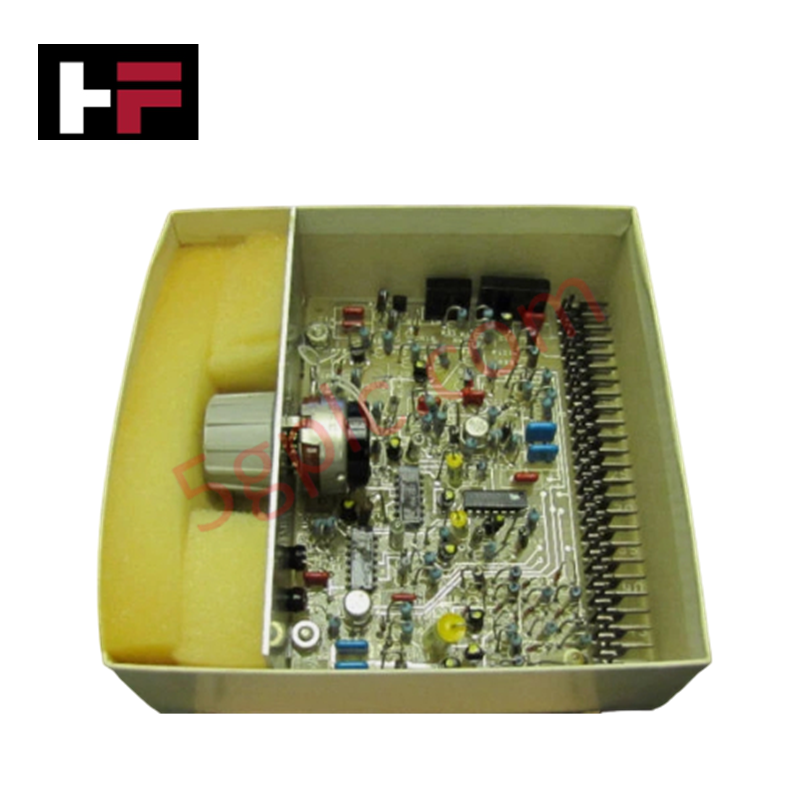
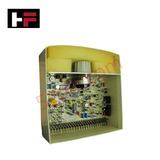
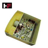
The GE IC3600SHPC101C, also cataloged as the IC3600SHPC Circuit Board, operates as a dedicated hardware component for analog signal processing and potentiometer-based parameter tuning within Speedtronic Mark I-II platforms.
Hardware Specifications
| Parameter | Specification |
|---|---|
| Model | IC3600SHPC101C |
| Brand | General Electric |
| Origin | USA |
| Weight | 0.45 kg |
| Dimensions | 220 x 150 x 30 mm |
| Operating Temp | 0 to 60 deg C |
| Power Consumption | 8 W |
| System Platform | Speedtronic Mark I / Mark II |
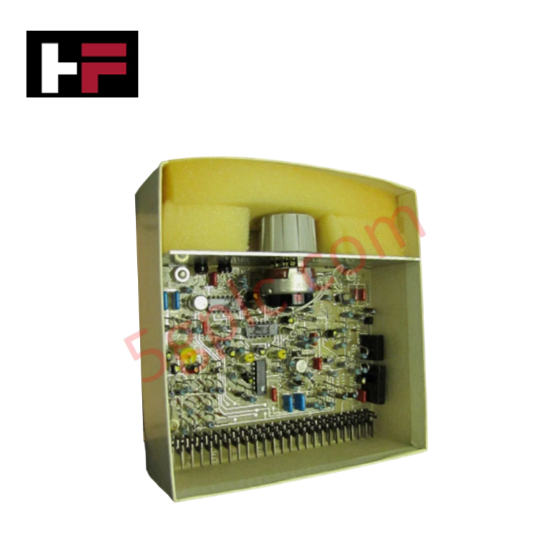
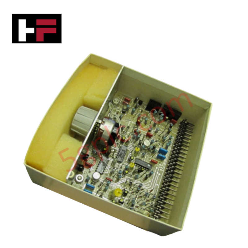
| Edge Interconnect | 51-pin card edge male prongs (labeled 1 to 51) |
| Onboard Adjustments | 1 x Large Potentiometer, 1 x Small Potentiometer, 1 x Center Grey Knob |
| Semiconductor Count | 3 x Integrated Circuits, 4 x Metallic Transistors |
| Capacitive Network | Yellow cylindrical capacitors (various sizes), Blue square capacitors |
| Structural Assembly | Left-side metal plate bracket |
Backplane Bus Communication Velocity and Firmware Flash Compatibility
The IC3600SHPC101C interfaces directly with the Mark I-II card rack backplane via its 51-pin edge connector interface. High-density trace routing links the integrated circuits and four metallic transistors to maintain stable backplane bus communication velocity across discrete analog control loops. Onboard potentiometers allow direct physical calibration of control setpoints, ensuring full hardware-level firmware flash compatibility across legacy Speedtronic card rack revisions without digital re-configuration.
Frequently Asked Questions
Q: How is physical alignment and ground bonding ensured during module insertion?
A: The board relies on its heavy-duty left-side metal plate bracket to align with the card cage guide tracks, ensuring firm contact across all 51 edge prongs.
Q: Are the onboard potentiometers used for software or hardware calibration?
A: The potentiometers and grey center knob provide direct analog circuit trim and hardware calibration for signal processing loops.
Q: What insulation precautions apply to the 51-pin edge connector prongs?
A: Edge prongs must remain free of oxidation and debris; clean contacts with isopropyl alcohol before insertion into the backplane connector frame.
Field Installation Guidelines
Completely remove main electrical power from the Speedtronic card rack prior to board removal or insertion. Wear a grounded wrist strap attached to unpainted enclosure steel to mitigate static discharge onto the onboard integrated circuits and metallic transistors. Align the board edges with the chassis card guides and slide the module straight back until the 51-pin edge connector fully seats into the backplane receptacle. Tighten any panel securing hardware hand-tight. Ensure field wiring connected to external card edge points follows strict separation from high-voltage AC lines.
Additional Information
- 100% Genuine Parts: All products are original and authentic, ensuring reliable industrial performance.
- 30-Day Refund Guarantee: Return any in-stock item within 30 days in original, unopened packaging for a full refund (excluding shipping and fees).
- 12-Month Warranty: Covers defects in materials or workmanship; excludes misuse, normal wear, or unauthorized modifications.
- Worldwide Shipping: We ship via USPS, UPS, FedEx, and DHL. Delivery times vary by country and may be subject to customs or import fees.
- Support & Contact: Technical and warranty assistance is available anytime. Contact us here: Contact.
- Purchase Guidance: Check product specifications and compatibility carefully before ordering to ensure proper application.


Tech & Buying Guide

Mastering the Siemens PLC Scan Cycle: How the CPU Executes Automation Programs
Industrial automation relies heavily on programmable logic controllers (PLCs) to manage complex manufacturing processes. Many engineers dive straight into programming without mastering the underlying architecture. However, understanding how a PLC CPU executes a program ensures reliable system design. Therefore, mastering the scan cycle optimizes both performance and troubleshooting in modern control systems.

How to Connect to Siemens S7 PLCs: 5 Essential Communication Methods
Establishing a reliable hardware link between a programming terminal and a Siemens SIMATIC controller is essential for engineering workflows. Field engineers rely on distinct physical layers, ranging from legacy serial connections to high-speed Industrial Ethernet protocols. Modern factory automation environments prioritize fast data transfer and seamless driver integration. Selecting the correct connection method simplifies program downloads, online monitoring, and system troubleshooting in complex control systems.

Will PLCs Become Obsolete? The Future of Control Systems in Industry 4.0
Modern manufacturing is undergoing a rapid technological transformation driven by Industry 4.0 innovations. Technologies like Artificial Intelligence (AI), Machine Learning (ML), and the Industrial Internet of Things (IIoT) are dominating discussions across the factory automation sector. Consequently, many engineers wonder if these advanced digital tools will eventually replace traditional Programmable Logic Controllers (PLCs). However, evaluating the core physics of industrial operations reveals a very different reality for control systems.