










Product Details
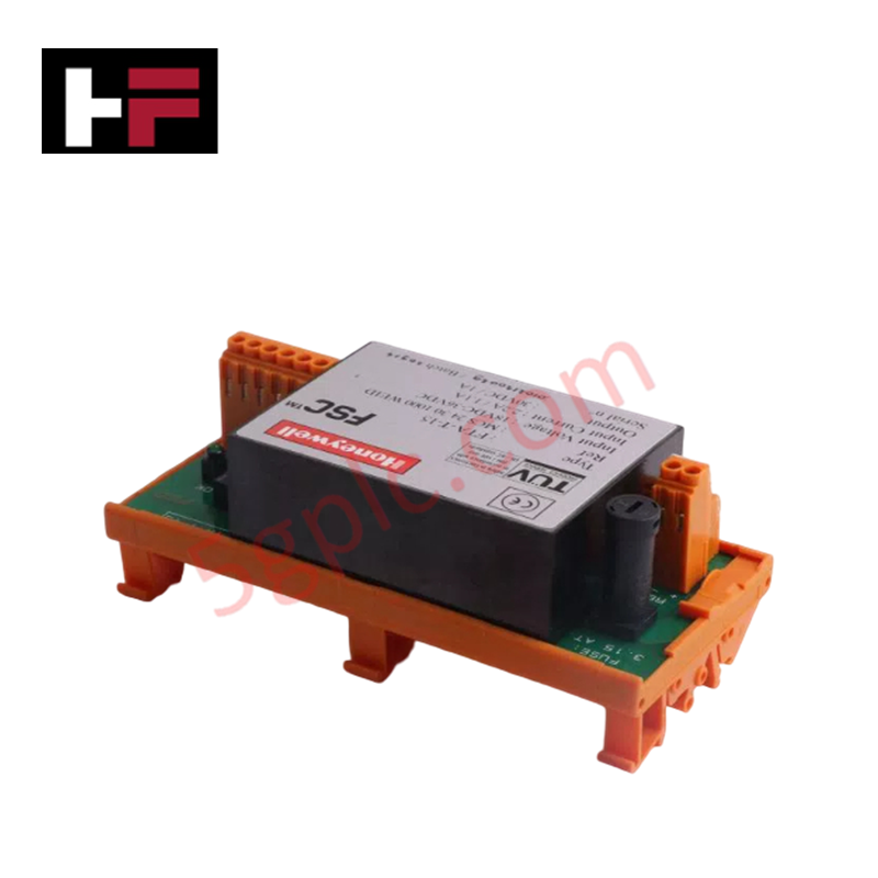
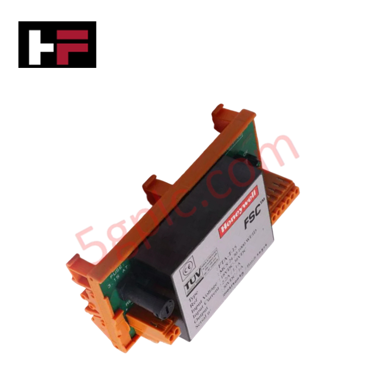
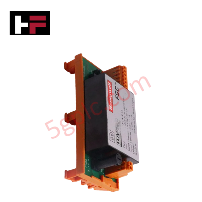
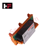
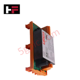
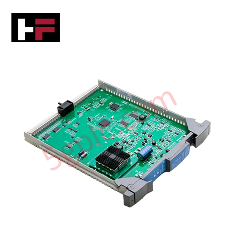
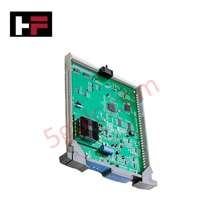
The Honeywell FTA-T-15, also cataloged as the FTA-T-15 Field Termination Assembly, operates as a dedicated hardware component for safe and structured field signal termination within Honeywell distributed control system networks.
Hardware Specifications
| Parameter | Specification |
|---|---|
| Model | FTA-T-15 |
| Brand | Honeywell |
| Origin | USA / As indicated on product label |
| Weight | 0.26 kg |
| Dimensions | 14.6 cm x 7 cm x 6.8 cm |
| Operating Temp | -40 to +70 deg C |
| Power Consumption | 24 VDC to 30 VDC operating supply voltage |
| Output Current | Maximum 1 A (Load capacity up to 5 A) |
| Isolation Voltage | 2000 VAC (input to output) |
| Communication Interface | Multi-point screw terminal blocks |
4-20 mA HART Loop & Channel-to-Channel Isolation Characteristics
Designed to provide high electrical isolation across field wiring boundaries, the termination module maintains 2000 VAC input-to-output isolation to prevent high-voltage surges from damaging central DCS processors. The internal printed circuit board trace topology preserves channel-to-channel isolation and prevents capacitive cross-talk on 4-20 mA HART analog loop connections. Integrated diagnostic circuits actively monitor field supply levels, triggering built-in overvoltage and undervoltage detection LED indicators when voltage thresholds deviate from operational limits.
Frequently Asked Questions
Q: Can this field termination assembly be mounted on standard DIN rails inside control cabinets?
A: Yes, the physical enclosure supports both standard DIN rail attachment and direct panel mounting.
Q: How does the built-in diagnostic detection signal overvoltage or undervoltage faults?
A: Integrated overvoltage and undervoltage monitoring circuits evaluate line levels and illuminate onboard LED indicators directly when supply voltage strays outside the 24 VDC to 30 VDC operating window.
Q: What is the dielectric isolation limit between field input terminals and control system outputs?
A: The internal barrier provides a rated isolation strength of 2000 VAC between input and output circuits.
Field Installation Guidelines
- Mount the assembly onto a 35 mm DIN rail or fasten securely to a panel plate using the designated mounting holes.
- Strip field conductor insulation to specified terminal length (typically 6 mm to 8 mm) before inserting wires into multi-point screw terminal blocks.
- Tighten terminal block screws to a torque rating of 0.5 Nm to ensure stable electrical contact without stripping threads.
- Route field 4-20 mA HART signal cables in dedicated raceways separated from high-voltage AC power lines.
- Ground the cable shield wire to the cabinet shield grounding bus bar at a single point to prevent ground loop currents.
Additional Information
- 100% Genuine Parts: All products are original and authentic, ensuring reliable industrial performance.
- 30-Day Refund Guarantee: Return any in-stock item within 30 days in original, unopened packaging for a full refund (excluding shipping and fees).
- 12-Month Warranty: Covers defects in materials or workmanship; excludes misuse, normal wear, or unauthorized modifications.
- Worldwide Shipping: We ship via USPS, UPS, FedEx, and DHL. Delivery times vary by country and may be subject to customs or import fees.
- Support & Contact: Technical and warranty assistance is available anytime. Contact us here: Contact.
- Purchase Guidance: Check product specifications and compatibility carefully before ordering to ensure proper application.
Tech & Buying Guide

PLC and DCS Control System Spares Strategy: Engineering Guidelines
Modern factory automation relies on high-speed fiber optic backbones to link distributed control systems across noise-intensive industrial environments. Unlike copper wiring, optical fibers transmit data via light pulses, making them completely immune to electromagnetic interference (EMI). Field engineers must master optical cable joining and fusion splicing techniques to guarantee low-loss data transmission across critical Programmable Logic Controller (PLC) and Distributed Control System (DCS) nodes.

PLC and DCS Control System Spares Strategy: Engineering Guidelines
Industrial automation lifecycle management requires robust spare parts planning for Programmable Logic Controller (PLC) and Distributed Control System (DCS) platforms. Plant engineers must correctly categorize spare components during front-end engineering design to maintain high system availability. Miscalculating spare requirements can lead to prolonged unscheduled downtime, project budget overruns, or delayed site commissioning.

Wellhead Control Panel (WHCP) Architecture in Oil and Gas Automation
Upstream oil and gas operations rely on specialized field control platforms to manage wellhead extraction safety and hydraulic actuation. A Wellhead Control Panel (WHCP) serves as a dedicated hydraulic and pneumatic power unit designed to operate critical Christmas Tree isolation valves. By interfacing field safety components directly with Programmable Logic Controller (PLC) architecture, a WHCP protects upstream extraction assets against overpressure, catastrophic leaks, and thermal emergencies.