










Product Details
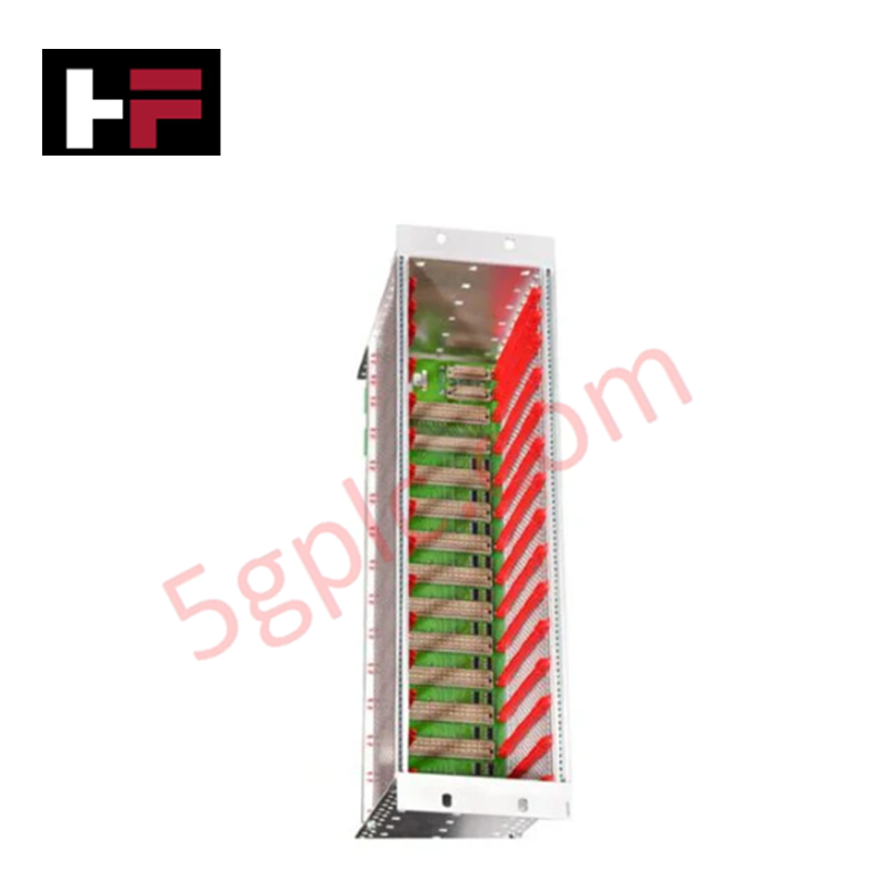
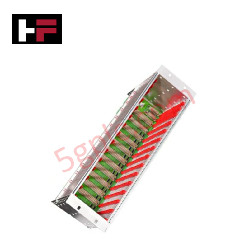
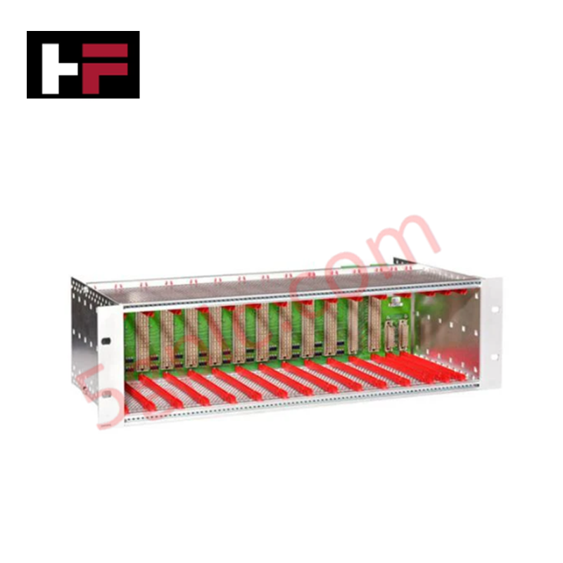
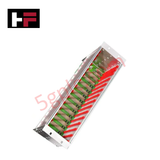
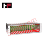
Configured for housing machinery protection and communication modules within AMS 6500 ATG systems, the EPRO A6500-SR (A6500-SR) System Rack provides direct physical/electrical execution for high-density sensor signal processing and management.
Hardware Specifications
| Parameter | Specification |
|---|---|
| Model | A6500-SR |
| Brand | EPRO |
| Dimensions | 19 inch (84HP width, 3RU height) |
| Operating Temp | -20 deg C to +70 deg C |
| Power Consumption | Not specified |
| Card Slots | 11 Protection, 1 Relay, 2 Communication |
| Connections | Screw terminals and D-Sub |
Process Control and DCS Connectivity
The A6500-SR rack serves as the primary backbone for the AMS 6500 ATG platform, supporting deterministic signal integration via dedicated A6500-CC communication cards. The rack provides robust channel-to-channel isolation between protection modules to ensure that individual sensor faults—such as those from eddy current or piezoelectric inputs—do not propagate across the backplane bus. Communication interfaces support Modbus TCP/IP, Modbus RTU, and OPC UA protocols, facilitating direct data exchange with DCS and SCADA networks. The system structure permits high-density I/O deployment while maintaining signal integrity for monitoring pulses, current outputs, and binary inputs.
Frequently Asked Questions
Q: Are the card slots hot-swappable during system operation?
A: The A6500-SR rack supports the insertion and removal of protection cards, but users must adhere to system-specific safety protocols regarding relay state management to prevent unintended trips or loss of monitoring during module replacement.
Q: How is the signal grounding managed for the D-Sub sensor inputs?
A: The rack architecture provides a common backplane reference. Ensure all sensor shields are terminated correctly at the D-Sub connector shells or dedicated grounding points on the rack to minimize EMI and maintain accurate signal referencing for the universal measuring cards.
Field Installation Guidelines
- Mount the 19" rack into a standard industrial enclosure, ensuring adequate clearance for 3RU height and proper convective airflow to manage heat dissipation.
- Terminate all field signals (RTDs, binary inputs, pulses) at the screw terminal connectors located on the rear panel.
- Utilize shielded D-Sub cabling for raw sensor signals to prevent signal degradation; ensure shield continuity to the rack ground point.
- Set the physical slide switches on the backplane or module cards to configure signal levels and binary input modes prior to energizing the system.
- Verify power connections to the redundant supply terminals before inserting active protection or communication modules into the rack slots.
Additional Information
- 100% Genuine Parts: All products are original and authentic, ensuring reliable industrial performance.
- 30-Day Refund Guarantee: Return any in-stock item within 30 days in original, unopened packaging for a full refund (excluding shipping and fees).
- 12-Month Warranty: Covers defects in materials or workmanship; excludes misuse, normal wear, or unauthorized modifications.
- Worldwide Shipping: We ship via USPS, UPS, FedEx, and DHL. Delivery times vary by country and may be subject to customs or import fees.
- Support & Contact: Technical and warranty assistance is available anytime. Contact us here: Contact.
- Purchase Guidance: Check product specifications and compatibility carefully before ordering to ensure proper application.




Tech & Buying Guide

Demystifying the DDE Protocol in Legacy Industrial Automation Systems
Modern control systems rely heavily on seamless interprocess communication to exchange operational data between software programs. Microsoft first introduced the Dynamic Data Exchange (DDE) protocol in 1987 to enable real-time data sharing. In factory automation, DDE served as an early bridge between control software and Windows desktop applications. Therefore, understanding DDE mechanics provides crucial insights into how legacy industrial networks established software-level connectivity.

Demystifying CPU Communication Ports in Siemens PLC Architectures
Industrial automation relies heavily on robust data exchange between devices. Without seamless connectivity, field instruments, network switches, human-machine interfaces, and programmable logic controllers cannot coordinate effectively. Therefore, understanding the various CPU communication ports available in Siemens hardware ensures efficient factory automation design and seamless system integration.

Mastering the Siemens PLC Scan Cycle: How the CPU Executes Automation Programs
Industrial automation relies heavily on programmable logic controllers (PLCs) to manage complex manufacturing processes. Many engineers dive straight into programming without mastering the underlying architecture. However, understanding how a PLC CPU executes a program ensures reliable system design. Therefore, mastering the scan cycle optimizes both performance and troubleshooting in modern control systems.