


Product Details
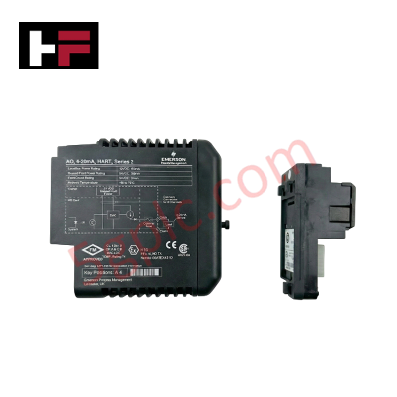
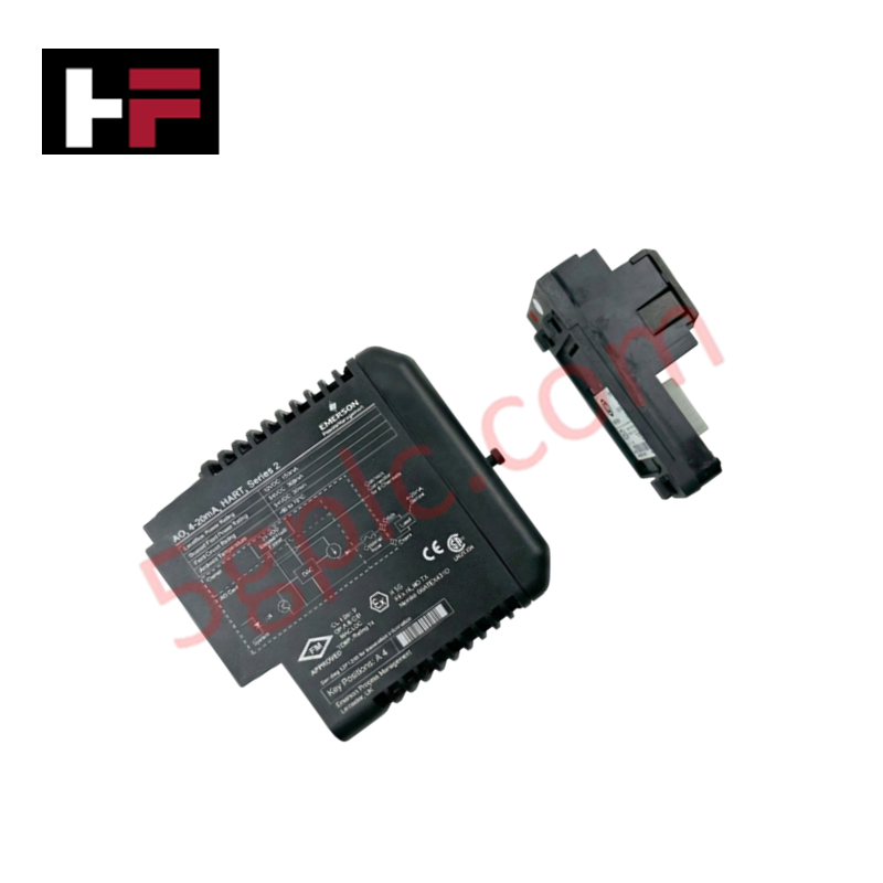
Configured for power distribution and signal isolation in DeltaV I/O subsystems, the Emerson VE5010 (VE5010, also cataloged as KJ4101X1-BC1) provides direct physical/electrical execution of intrinsically safe power regulation for hazardous area instrumentation.
Hardware Specifications
| Parameter | Specification |
| Model | VE5010 |
| Brand | Emerson |
| Origin | USA |
| Weight | 0.82 kg (1.8 lbs) |
| Dimensions | 93 mm x 168 mm x 35 mm |
| Operating Temp | Not specified |
| Power Consumption | Passive distribution |
| Input Rating | 24 VDC |
| Function | IS Power Supply Carrier |
Process Control: Intrinsic Safety (Ex i) Barriers
The VE5010 carrier serves as a foundational component for implementing intrinsic safety within the DeltaV architecture. It facilitates the distribution of power to connected I/O modules while maintaining stringent energy-limiting barriers that prevent ignition-capable electrical or thermal energy from entering hazardous areas. The carrier is engineered to support Ex i compliance, ensuring that field-side circuits are galvanically isolated from the non-hazardous control bus. This implementation requires meticulous adherence to loop-drawing specifications and cable capacitance/inductance limits to maintain the safety integrity of the installed field instruments.
Frequently Asked Questions (FAQ)
Q: Can the VE5010 be used for non-intrinsically safe I/O modules?
A: The VE5010 is specifically designed for use with intrinsically safe DeltaV I/O modules. Use with non-IS modules will negate the intended safety protection and may result in improper module operation or damage to the carrier backplane.
Q: What is the recommended mounting configuration?
A: The module supports DIN-rail or panel mounting. Ensure that the mounting surface is grounded and that the module is installed in an environment free from excessive vibration, which could compromise the electrical contact between the module and the carrier backplane pins.
Field Installation Guidelines
-
Mounting: Secure the carrier to the DIN rail or panel using appropriate fastening hardware. Maintain adequate spacing between the VE5010 and non-IS components to prevent unintended coupling or mechanical interference.
-
Wiring: Terminate 24 VDC input power at the carrier power terminals. All field wiring must be routed according to local hazardous area installation codes, strictly segregating IS and non-IS circuits to prevent cross-talk or short-circuit failures.
-
Grounding: Bond the carrier chassis to the system earth ground. A low-impedance ground path is mandatory to ensure the stability of the safety barriers and to suppress electromagnetic noise that could interfere with signal precision.
-
Verification: After installation, measure the output voltage at the module connection points to ensure proper power delivery. Conduct a continuity test on all field loops to verify isolation from ground and ensure that field device capacitance and inductance parameters conform to the system safety design.
Additional Information
- 100% Genuine Parts: All products are original and authentic, ensuring reliable industrial performance.
- 30-Day Refund Guarantee: Return any in-stock item within 30 days in original, unopened packaging for a full refund (excluding shipping and fees).
- 12-Month Warranty: Covers defects in materials or workmanship; excludes misuse, normal wear, or unauthorized modifications.
- Worldwide Shipping: We ship via USPS, UPS, FedEx, and DHL. Delivery times vary by country and may be subject to customs or import fees.
- Support & Contact: Technical and warranty assistance is available anytime. Contact us here: Contact.
- Purchase Guidance: Check product specifications and compatibility carefully before ordering to ensure proper application.


Tech & Buying Guide

Essential Motion Control Commands: A Practical Guide for Engineers
Automation engineers often rely on precise position and speed control to drive modern factory machinery. Modern industrial systems, such as Programmable Logic Controllers (PLCs) and Distributed Control Systems (DCS), depend heavily on standardized motion instructions. Mastering these commands ensures operational safety, protects mechanical components, and optimizes cycle times across production lines.

The Role of Intrinsic Safety Barriers in PLC and DCS Architectures
Implementing robust protection in hazardous industrial environments represents a fundamental safety requirement in factory automation. Process facilities often handle volatile gases, dusts, and chemical agents that pose significant combustion risks. Consequently, control system engineers must deploy energy-limiting interfaces to isolate safe-area control cabinets from hazardous-area field instrumentation. This article examines the function, selection, and electrical principles of intrinsic safety barriers within modern PLC and DCS networks.

Architectural Selection and Scale Classification of PLC Systems in Industrial Automation
Selecting the correct control platform represents a foundational engineering decision in factory automation. System designers must carefully balance technical parameters against long-term operational requirements when implementing a Programmable Logic Controller (PLC). This article examines the critical evaluation metrics, physical scale classifications, and operational architectures of modern control systems.