


Product Details
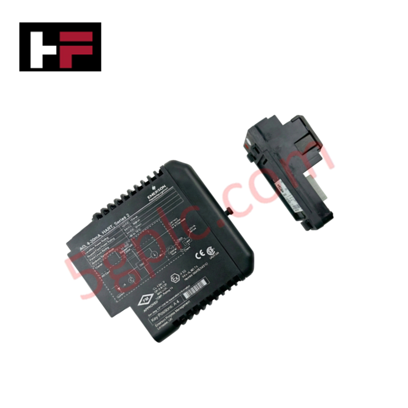
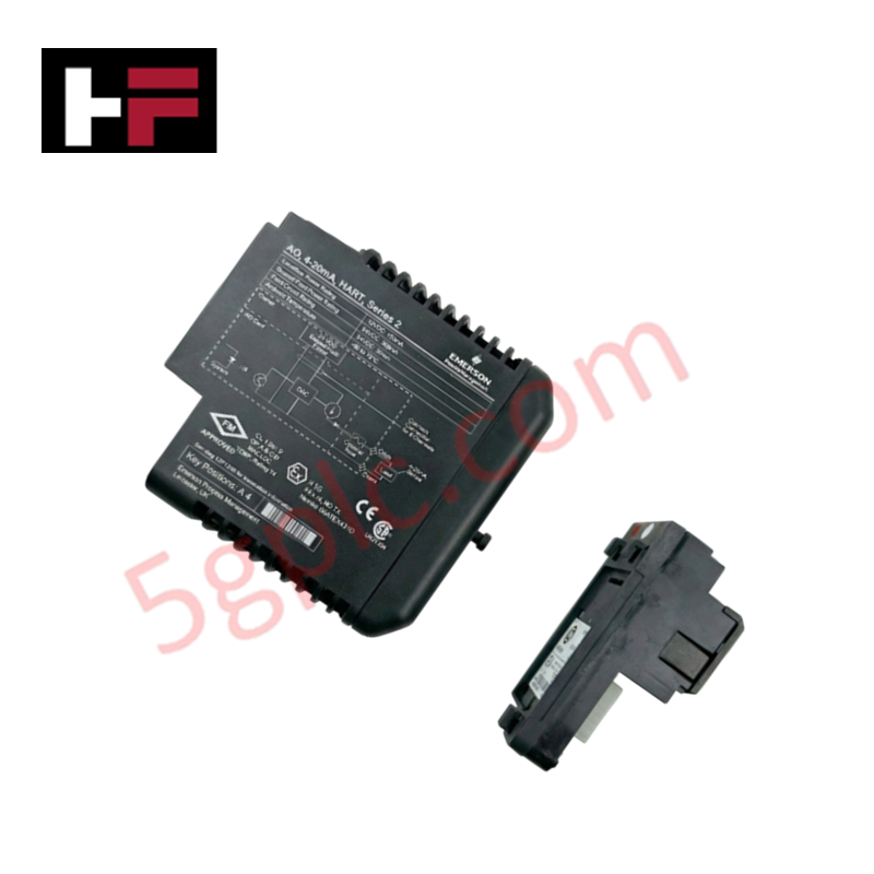
Configured for analog signal output in DeltaV I/O subsystems, the Emerson VE4005S2B1 (VE4005S2B1) Analog Output Termination Block provides direct physical/electrical execution of 8-channel 4-20 mA control signal distribution.
Hardware Specifications
| Parameter | Specification |
| Model | VE4005S2B1 |
| Brand | Emerson |
| Origin | USA |
| Weight | 2.0 kg |
| Dimensions | Standard M-series block footprint |
| Operating Temp | Not specified |
| Power Consumption | Passive distribution |
| Channel Count | 8 channels |
| Signal Type | 4-20 mA |
Process Control: Channel-to-Channel Isolation
The VE4005S2B1 termination block facilitates signal distribution while maintaining channel-to-channel isolation on the DeltaV I/O carrier. This structural isolation prevents ground loops and electrical interference from propagating between parallel output loops. By physically separating the 4-20 mA signal paths, the block ensures that transient voltages or fault conditions in one actuator circuit do not affect the control signal integrity of adjacent channels. This design maintains the electrical performance of the analog output card, ensuring deterministic loop current regulation across all 8 channels.
Frequently Asked Questions (FAQ)
Q: Does this termination block support field-side loop power?
A: The VE4005S2B1 is a passive termination component designed to route signals from the analog output card to the field devices. Any required loop power must be provided by the system power supply via the I/O carrier backplane or external sources, depending on the specific loop configuration.
Q: Is this block hot-swappable during system operation?
A: The VE4005S2B1 is designed for use on DeltaV M-series carriers that support hot-swapping. However, ensure that the corresponding analog output channel is placed in a safe state or manual control mode within the DeltaV software before physical removal to prevent uncontrolled actuator movement.
Field Installation Guidelines
-
Mounting: Snap the termination block onto the M-series I/O carrier. Ensure the mechanical keying pins align correctly to verify that the block is locked into the intended slot position.
-
Wiring: Use shielded twisted pair cabling for all 4-20 mA loops to minimize electromagnetic interference. Terminate cable shields at the designated ground lug on the carrier to ensure a low-impedance reference to the cabinet ground.
-
Tightening: Tighten all terminal screws to the specified torque. Avoid over-torquing, which may cause mechanical damage to the terminal block's internal contact plates.
-
Verification: Prior to commissioning, verify loop continuity and polarity. Confirm that the 4-20 mA output current matches the commanded values from the controller by measuring the current in series with the field loop.
Additional Information
- 100% Genuine Parts: All products are original and authentic, ensuring reliable industrial performance.
- 30-Day Refund Guarantee: Return any in-stock item within 30 days in original, unopened packaging for a full refund (excluding shipping and fees).
- 12-Month Warranty: Covers defects in materials or workmanship; excludes misuse, normal wear, or unauthorized modifications.
- Worldwide Shipping: We ship via USPS, UPS, FedEx, and DHL. Delivery times vary by country and may be subject to customs or import fees.
- Support & Contact: Technical and warranty assistance is available anytime. Contact us here: Contact.
- Purchase Guidance: Check product specifications and compatibility carefully before ordering to ensure proper application.


Tech & Buying Guide

Essential Motion Control Commands: A Practical Guide for Engineers
Automation engineers often rely on precise position and speed control to drive modern factory machinery. Modern industrial systems, such as Programmable Logic Controllers (PLCs) and Distributed Control Systems (DCS), depend heavily on standardized motion instructions. Mastering these commands ensures operational safety, protects mechanical components, and optimizes cycle times across production lines.

The Role of Intrinsic Safety Barriers in PLC and DCS Architectures
Implementing robust protection in hazardous industrial environments represents a fundamental safety requirement in factory automation. Process facilities often handle volatile gases, dusts, and chemical agents that pose significant combustion risks. Consequently, control system engineers must deploy energy-limiting interfaces to isolate safe-area control cabinets from hazardous-area field instrumentation. This article examines the function, selection, and electrical principles of intrinsic safety barriers within modern PLC and DCS networks.

Architectural Selection and Scale Classification of PLC Systems in Industrial Automation
Selecting the correct control platform represents a foundational engineering decision in factory automation. System designers must carefully balance technical parameters against long-term operational requirements when implementing a Programmable Logic Controller (PLC). This article examines the critical evaluation metrics, physical scale classifications, and operational architectures of modern control systems.