


Product Details
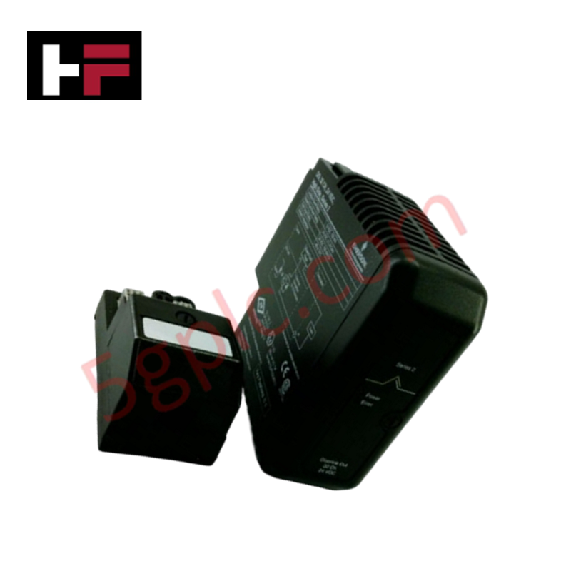
Configured for analog signal acquisition in DeltaV I/O subsystems, the Emerson VE4003S2B2 (VE4003S2B2 Fused I/O Termination Block) provides direct physical/electrical execution of 4-20 mA HART signal monitoring.
Hardware Specifications
| Parameter | Specification |
| Model | VE4003S2B2 |
| Brand | Emerson |
| Origin | USA |
| Weight | 0.73 kg (1.60 lbs) |
| Dimensions | Standard M-series termination block |
| Operating Temp | Not specified |
| Power Consumption | Passive field power distribution |
| Channel Count | 8 channels |
| Signal Range | 4-20 mA HART |
Process Control: 4-20 mA HART Loop Protocol
The VE4003S2B2 block supports the 4-20 mA HART loop protocol, enabling digital communication overlay for transmitter diagnostics and configuration. The module is architected for both 2-wire and 4-wire transmitter configurations, selectable via jumper or terminal wiring. Internal circuitry maintains channel-to-channel isolation, preventing signal interference between individual loops. The block operates within a 12-24 VDC range to provide field loop power, ensuring compliant transmission of both the analog process variable and the frequency-shift keying (FSK) digital HART data to the DeltaV I/O card.
Frequently Asked Questions (FAQ)
Q: Can this termination block be configured for different transmitter wiring types?
A: Yes. The VE4003S2B2 supports both 2-wire and 4-wire transmitter connections. Ensure the field wiring matches the selected input configuration to prevent loop power supply damage or signal clipping.
Q: What is the purpose of the "Key Positions A 1" designation?
A: This is a mechanical keying setting specific to the M-series carrier. It prevents the installation of incorrect I/O card types into this terminal block, ensuring that high-voltage or incompatible signal types are not inadvertently connected to the analog input circuitry.
Field Installation Guidelines
-
Mounting: Seat the termination block onto the M-series carrier. Verify that the keying pins are set to position A 1 as required by the I/O card configuration to permit proper latching.
-
Wiring: Use shielded twisted pair cables for all analog signal runs. Ground the shield at the cabinet entry point using an approved grounding bar to minimize electromagnetic interference on the 4-20 mA loops.
-
Termination: Ensure all terminal screws are tightened to the specified torque. High-resistance connections can introduce voltage drops that affect the accuracy of the 4-20 mA measurement.
-
Verification: Check for correct loop voltage (12-24 VDC) at the terminals prior to connecting the field instrument. If HART communication is intermittent, verify that the load resistance on the loop falls within the required specifications for FSK signal transmission.
Additional Information
- 100% Genuine Parts: All products are original and authentic, ensuring reliable industrial performance.
- 30-Day Refund Guarantee: Return any in-stock item within 30 days in original, unopened packaging for a full refund (excluding shipping and fees).
- 12-Month Warranty: Covers defects in materials or workmanship; excludes misuse, normal wear, or unauthorized modifications.
- Worldwide Shipping: We ship via USPS, UPS, FedEx, and DHL. Delivery times vary by country and may be subject to customs or import fees.
- Support & Contact: Technical and warranty assistance is available anytime. Contact us here: Contact.
- Purchase Guidance: Check product specifications and compatibility carefully before ordering to ensure proper application.


Tech & Buying Guide

Essential Motion Control Commands: A Practical Guide for Engineers
Automation engineers often rely on precise position and speed control to drive modern factory machinery. Modern industrial systems, such as Programmable Logic Controllers (PLCs) and Distributed Control Systems (DCS), depend heavily on standardized motion instructions. Mastering these commands ensures operational safety, protects mechanical components, and optimizes cycle times across production lines.

The Role of Intrinsic Safety Barriers in PLC and DCS Architectures
Implementing robust protection in hazardous industrial environments represents a fundamental safety requirement in factory automation. Process facilities often handle volatile gases, dusts, and chemical agents that pose significant combustion risks. Consequently, control system engineers must deploy energy-limiting interfaces to isolate safe-area control cabinets from hazardous-area field instrumentation. This article examines the function, selection, and electrical principles of intrinsic safety barriers within modern PLC and DCS networks.

Architectural Selection and Scale Classification of PLC Systems in Industrial Automation
Selecting the correct control platform represents a foundational engineering decision in factory automation. System designers must carefully balance technical parameters against long-term operational requirements when implementing a Programmable Logic Controller (PLC). This article examines the critical evaluation metrics, physical scale classifications, and operational architectures of modern control systems.