


Product Details
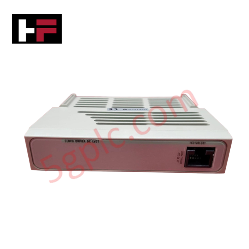
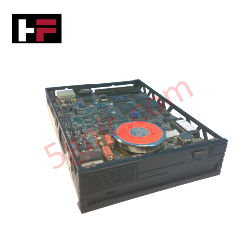
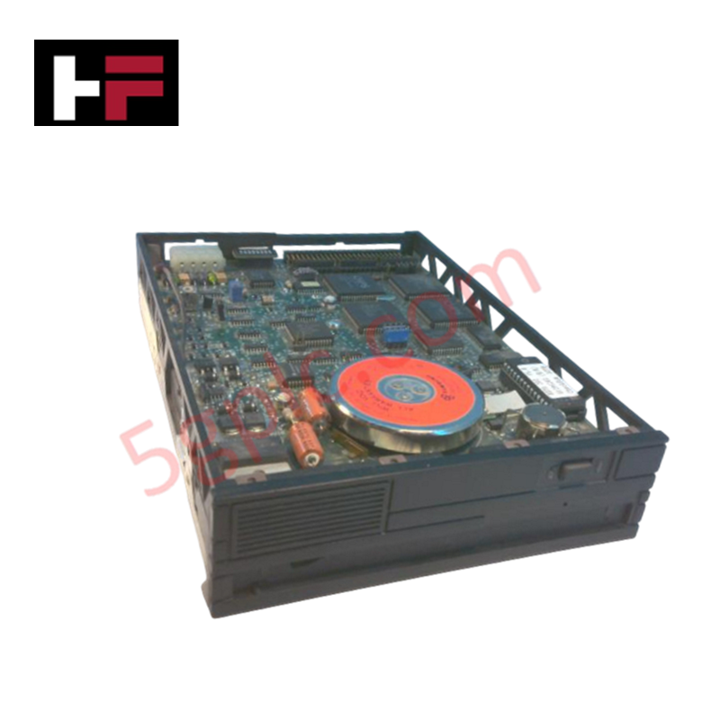
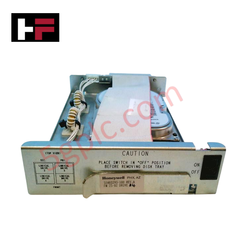
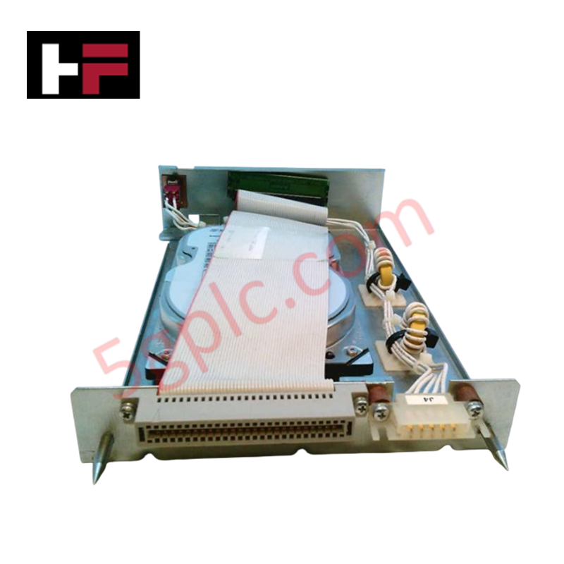
Configured for actuator control within Ovation distributed control systems, the Emerson 1C31201G01 (1C31201G01 Driver Electronics Module) provides direct physical electrical execution for driving industrial field devices. This module facilitates the processing of command signals necessary to regulate positioner output or servo-actuator response across control loops.
Hardware Specifications
| Parameter | Specification |
|---|---|
| Model | 1C31201G01 |
| Brand | Emerson |
| Origin | United States |
| Weight | 2 kg |
| Dimensions | 30.0 cm x 20.0 cm x 20.0 cm |
| Operating Temp | Not Specified |
| Power Consumption | Not Specified |
| Module Type | Driver Electronics Module |
Process Control Connectivity and Signal Integrity
The 1C31201G01 architecture supports robust channel-to-channel isolation, which is required to prevent electrical noise propagation between the control bus and the field-side actuator circuitry. This design minimizes the risk of common-mode interference affecting output signal stability during high-demand control maneuvers. The module enables seamless integration with 4-20 mA HART loop protocol standards, allowing for the transmission of diagnostic information from intelligent field devices back to the controller, thereby maintaining visibility into the health and status of the controlled loop.
Frequently Asked Questions (FAQ)
Q: Does the 1C31201G01 module support hot-swapping during normal system operation?
A: The module supports hot-swap functionality within the Ovation rack architecture. Ensure the control loop is isolated and the system configuration is set to maintenance mode prior to module extraction to prevent unexpected actuator output transitions.
Q: How should the module be configured for specific actuator load requirements?
A: Load-specific parameters are configured within the Ovation controller software; verify that the hardware revision is compatible with the intended application firmware version to ensure proper output characteristics.
Field Installation Guidelines
- Confirm the backplane is powered before installing the module to ensure proper connector alignment and seating.
- Align the module housing with the chassis rails and press firmly until the mechanical latch engages with the rack structure.
- Terminate signal and feedback wiring at the terminal block; use shielded, twisted-pair cables to maintain signal fidelity and reduce EMI.
- Bond all shield drain wires to the cabinet ground bus at a single reference point to mitigate ground loops.
- Verify the module status via front-panel LEDs to confirm valid communication with the backplane bus upon power-up.
Additional Information
- 100% Genuine Parts: All products are original and authentic, ensuring reliable industrial performance.
- 30-Day Refund Guarantee: Return any in-stock item within 30 days in original, unopened packaging for a full refund (excluding shipping and fees).
- 12-Month Warranty: Covers defects in materials or workmanship; excludes misuse, normal wear, or unauthorized modifications.
- Worldwide Shipping: We ship via USPS, UPS, FedEx, and DHL. Delivery times vary by country and may be subject to customs or import fees.
- Support & Contact: Technical and warranty assistance is available anytime. Contact us here: Contact.
- Purchase Guidance: Check product specifications and compatibility carefully before ordering to ensure proper application.

Tech & Buying Guide

Essential Motion Control Commands: A Practical Guide for Engineers
Automation engineers often rely on precise position and speed control to drive modern factory machinery. Modern industrial systems, such as Programmable Logic Controllers (PLCs) and Distributed Control Systems (DCS), depend heavily on standardized motion instructions. Mastering these commands ensures operational safety, protects mechanical components, and optimizes cycle times across production lines.

The Role of Intrinsic Safety Barriers in PLC and DCS Architectures
Implementing robust protection in hazardous industrial environments represents a fundamental safety requirement in factory automation. Process facilities often handle volatile gases, dusts, and chemical agents that pose significant combustion risks. Consequently, control system engineers must deploy energy-limiting interfaces to isolate safe-area control cabinets from hazardous-area field instrumentation. This article examines the function, selection, and electrical principles of intrinsic safety barriers within modern PLC and DCS networks.

Architectural Selection and Scale Classification of PLC Systems in Industrial Automation
Selecting the correct control platform represents a foundational engineering decision in factory automation. System designers must carefully balance technical parameters against long-term operational requirements when implementing a Programmable Logic Controller (PLC). This article examines the critical evaluation metrics, physical scale classifications, and operational architectures of modern control systems.