










Product Details
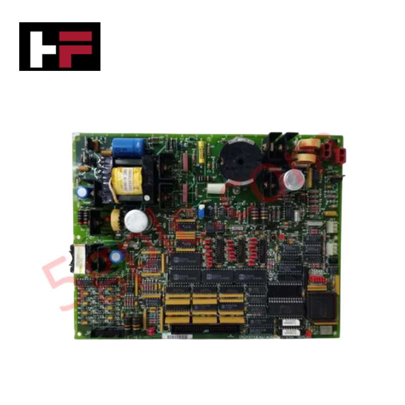
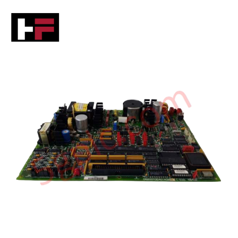
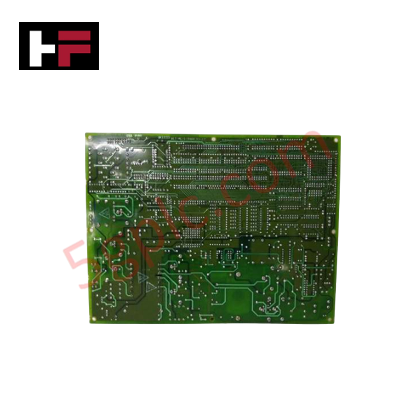
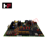
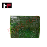
Configured for turbine protection and frequency monitoring within Mark V Speedtronic systems, the GE DS200TCEAG1A (DS200TCEA Emergency Over Speed Board) provides direct physical/electrical execution of safety-critical speed trip logic.
Hardware Specifications
| Parameter | Specification |
|---|---|
| Model | DS200TCEAG1A |
| Brand | GE General Electric |
| Origin | USA |
| Dimensions | Standard Mark V PCB footprint |
| Operating Temp | Per Mark V environmental requirements |
| Power Consumption | Backplane rail supply |
| Components | 1 x microprocessor, 3 x fuses, 30 x jumpers |
Industrial Control and Firmware Compatibility
The DS200TCEAG1A utilizes a microprocessor-based architecture to monitor turbine rotational frequency and execute emergency shutdown sequences. Firmware flash compatibility is managed via removable PROM modules that house the CPU instruction set. The board assembly requires specific backplane bus communication velocity settings to ensure synchronized monitoring across the turbine control rack. Proper I/O density scaling is achieved through the integration of the TCE board within the protection core, where it interfaces with speed sensors to trigger trip logic based on predefined frequency thresholds.
Frequently Asked Questions
Q: Are PROM modules included with a replacement board?
A: No. Replacement boards are shipped with unpopulated PROM sockets. Users must transfer the original PROM modules from the failed board to the replacement board to ensure identical instruction sets and control logic are maintained.
Q: What is the function of the 30 jumpers on the board?
A: The jumpers are factory-configured to define board address, protection threshold logic, and communication parameters. These should be set to match the configuration of the original board.
Field Installation Guidelines
- Static Discharge Protection: PROM modules are highly sensitive to electrostatic discharge. Always wear a properly grounded anti-static wrist strap when handling the board or the modules. Ensure the wrist strap clip is attached to a verified earth-grounded metal surface.
- Module Transfer: When moving PROM modules, verify pin alignment and notch orientation before seating them into the sockets on the new board. Ensure firm, even pressure is applied to avoid bending pins.
- Fuse Inspection: The board includes 3 fuses for circuit protection. If the board fails to power up or process inputs, check these fuses for continuity before proceeding with further diagnostics.
- Mounting: Ensure the board is fully seated in the designated Mark V rack slot. Utilize the bayonet connections to lock the board into the chassis, ensuring a secure electrical interface with the backplane.
- Jumper Verification: Before energizing the system, compare the jumper configuration on the replacement board against the original to ensure identical protection logic is enforced.
Additional Information
- 100% Genuine Parts: All products are original and authentic, ensuring reliable industrial performance.
- 30-Day Refund Guarantee: Return any in-stock item within 30 days in original, unopened packaging for a full refund (excluding shipping and fees).
- 12-Month Warranty: Covers defects in materials or workmanship; excludes misuse, normal wear, or unauthorized modifications.
- Worldwide Shipping: We ship via USPS, UPS, FedEx, and DHL. Delivery times vary by country and may be subject to customs or import fees.
- Support & Contact: Technical and warranty assistance is available anytime. Contact us here: Contact.
- Purchase Guidance: Check product specifications and compatibility carefully before ordering to ensure proper application.


Tech & Buying Guide

Mastering the Siemens PLC Scan Cycle: How the CPU Executes Automation Programs
Industrial automation relies heavily on programmable logic controllers (PLCs) to manage complex manufacturing processes. Many engineers dive straight into programming without mastering the underlying architecture. However, understanding how a PLC CPU executes a program ensures reliable system design. Therefore, mastering the scan cycle optimizes both performance and troubleshooting in modern control systems.

How to Connect to Siemens S7 PLCs: 5 Essential Communication Methods
Establishing a reliable hardware link between a programming terminal and a Siemens SIMATIC controller is essential for engineering workflows. Field engineers rely on distinct physical layers, ranging from legacy serial connections to high-speed Industrial Ethernet protocols. Modern factory automation environments prioritize fast data transfer and seamless driver integration. Selecting the correct connection method simplifies program downloads, online monitoring, and system troubleshooting in complex control systems.

Will PLCs Become Obsolete? The Future of Control Systems in Industry 4.0
Modern manufacturing is undergoing a rapid technological transformation driven by Industry 4.0 innovations. Technologies like Artificial Intelligence (AI), Machine Learning (ML), and the Industrial Internet of Things (IIoT) are dominating discussions across the factory automation sector. Consequently, many engineers wonder if these advanced digital tools will eventually replace traditional Programmable Logic Controllers (PLCs). However, evaluating the core physics of industrial operations reveals a very different reality for control systems.