










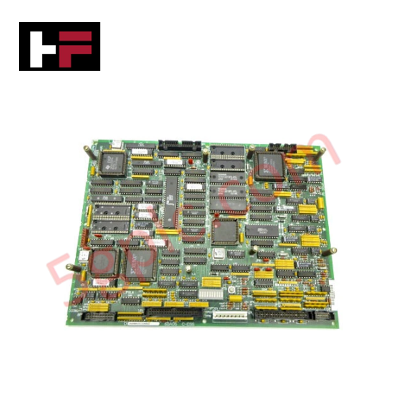
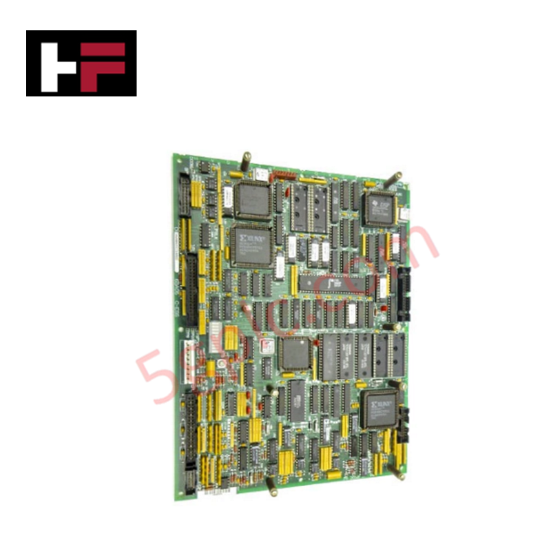
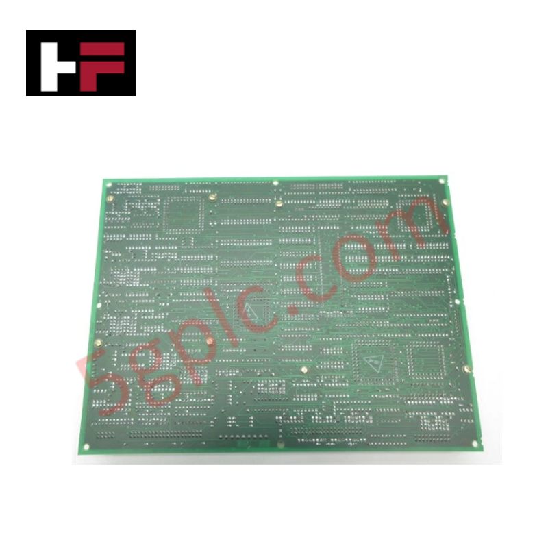
Product Details
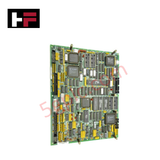
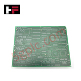
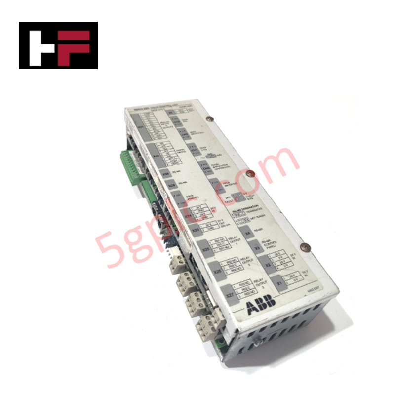
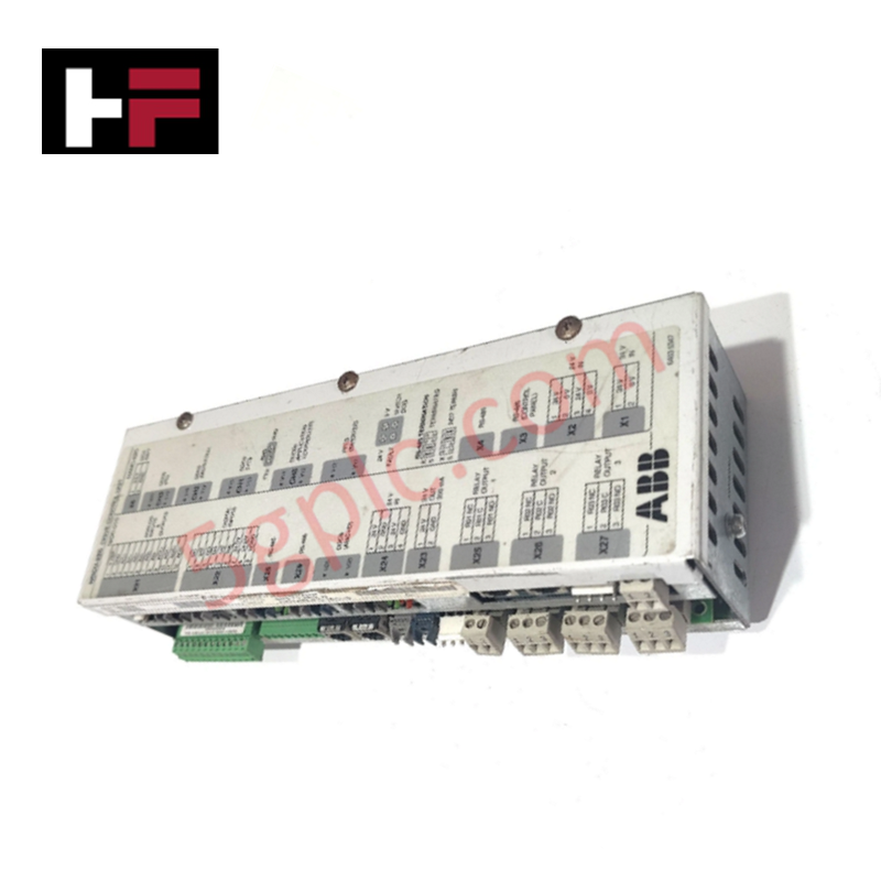
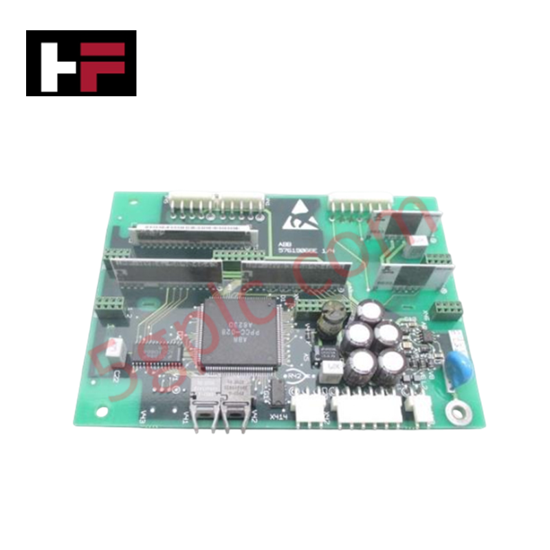
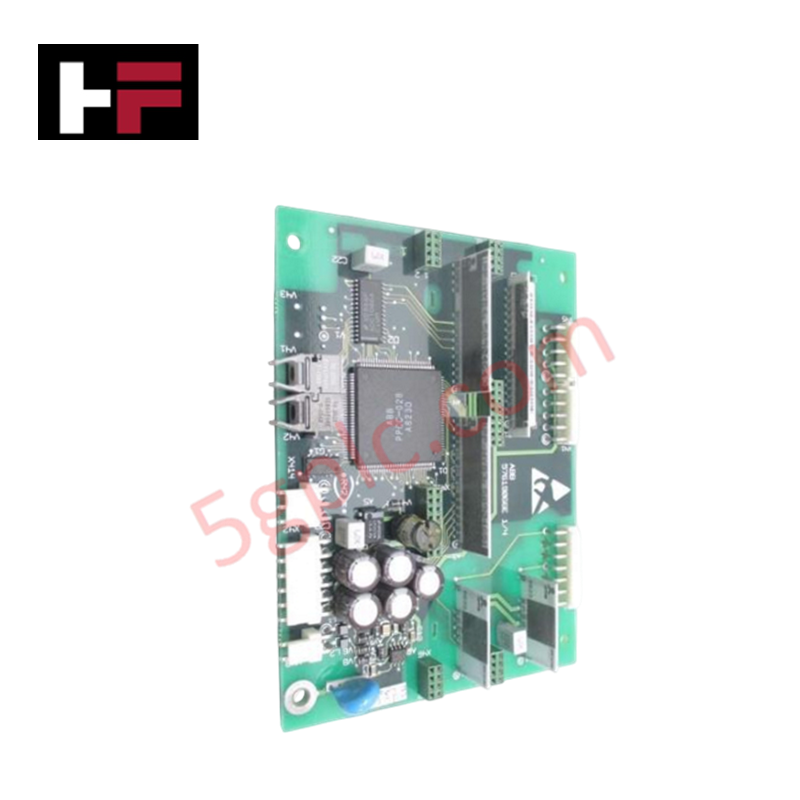
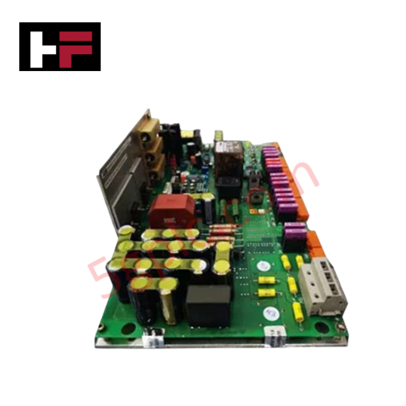
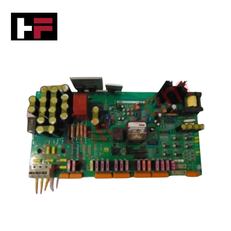
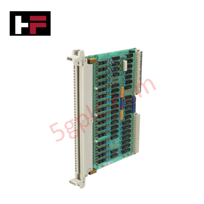
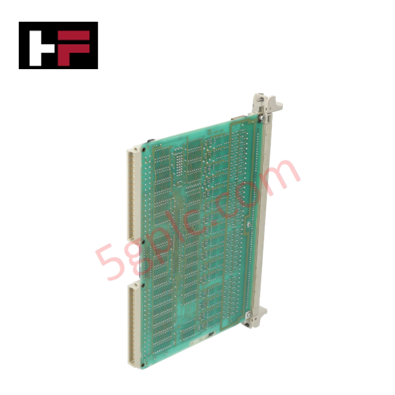
Configured for primary regulation and management in Mark V Speedtronic systems, the GE DS200SDCCG4AGD (DS200SDCCG4 Drive Control Card) provides direct physical processing of control loops and drive management signals.
Hardware Specifications
| Parameter | Specification |
|---|---|
| Model | DS200SDCCG4AGD |
| Brand | General Electric |
| Origin | USA |
| Weight | 0.36 kg |
| Dimensions | 8.2 cm x 12.2 cm x 6 cm |
| Core Components | 3 microprocessors, dual-ported RAM, 10-LED diagnostic array |
Industrial Control & Firmware Compatibility
The DS200SDCCG4AGD utilizes a tri-processor architecture to execute real-time motor control and drive management tasks. Deterministic operation is predicated on backplane bus communication velocity, ensuring synchronized data exchange between the processors. Firmware flash compatibility is managed at the system level, requiring the host drive to maintain parity with the SDCC hardware revision. I/O density scaling is achieved via the board's interface connectors, which establish dedicated paths for I/O signal distribution and DC voltage input from the Power Supply Interface Board. Users must ensure that configuration parameters match the specific turbine drive assembly to avoid logic-level synchronization faults.
Frequently Asked Questions
Q: How are diagnostic error codes interpreted via the onboard LEDs?
A: The 10-row LED array displays error codes in a three-part flash sequence. The first two LEDs represent the hundreds digit, the next four represent the tens digit, and the final four represent the units digit. A sequential left-to-right flash pattern indicates normal operating status or standby mode.
Q: What are the primary connection requirements for this control card?
A: The board features two dedicated connectors for interfacing with the Power Supply Interface Board. One connector is dedicated to I/O signal transmission, while the second provides the necessary DC voltage supply from the interface board to the control card.
Field Installation Guidelines
- Personnel Safety: Before opening the drive cabinet, ensure the system is completely de-energized. The internal components operate at high energy levels; accidental contact with the PCB surface or surrounding drive components can cause severe electrical shock or burns.
- Component Handling: Access the board from the front-facing drive cabinet door. Use grounded tools and ESD-mitigation straps to prevent electrostatic damage to the onboard integrated circuits and microprocessors.
- Visual Diagnostics: During startup, verify the LED sequence. If the error code display indicates a fault, record the numerical flash pattern according to the GEI-100029 manual before attempting to reset the control card or re-initialize the drive parameters.
- Signal Integrity: Ensure all harness connectors are fully latched. Loose connectors at the Power Supply Interface Board interface will result in unregulated DC voltage input or intermittent loss of I/O signal data.
Additional Information
- 100% Genuine Parts: All products are original and authentic, ensuring reliable industrial performance.
- 30-Day Refund Guarantee: Return any in-stock item within 30 days in original, unopened packaging for a full refund (excluding shipping and fees).
- 12-Month Warranty: Covers defects in materials or workmanship; excludes misuse, normal wear, or unauthorized modifications.
- Worldwide Shipping: We ship via USPS, UPS, FedEx, and DHL. Delivery times vary by country and may be subject to customs or import fees.
- Support & Contact: Technical and warranty assistance is available anytime. Contact us here: Contact.
- Purchase Guidance: Check product specifications and compatibility carefully before ordering to ensure proper application.
Tech & Buying Guide

Spatial Computing in Industrial Automation: Elevating PLC and DCS Operations with AR and VR
Industry 4.0 integrates digital intelligence into field operations, transforming factory automation landscapes worldwide. Spatial technologies—specifically Augmented Reality (AR) and Virtual Reality (VR)—redefine how engineers interact with industrial control systems. By bridging computer-generated CAD models with real-time operational technology (OT) data, immersive displays enable intuitive monitoring, rapid diagnostics, and safer maintenance across complex processing facilities.

Master Acceptance Testing: Understanding FAT and SAT in Industrial Control Systems
Factory Acceptance Testing (FAT) and Site Acceptance Testing (SAT) serve as critical quality assurance gateways in complex industrial control systems. Both procedures verify that programmable logic controllers (PLCs), distributed control systems (DCS), and associated field devices meet strict functional specifications. However, executing these tests effectively requires clear delineation between off-site staging and final field commissioning.

Industrial Networking Essentials: Demystifying Hubs, Switches, and Routers in Control Systems
Industrial automation relies heavily on robust networking infrastructure to connect programmable logic controllers (PLCs), distributed control systems (DCS), and human-machine interfaces (HMIs). Modern factory automation environments generate vast amounts of real-time operational data across deterministic networks. Understanding the structural differences between hubs, switches, and routers ensures optimal traffic segmentation, minimizes latency, and maintains high network availability.