










Product Details
Product Overview
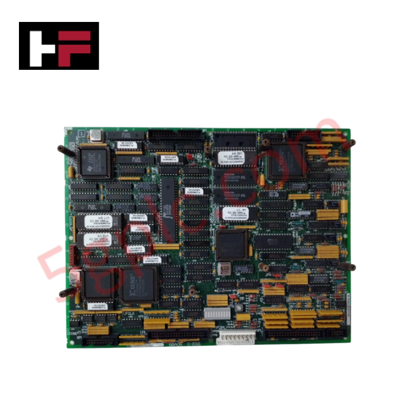
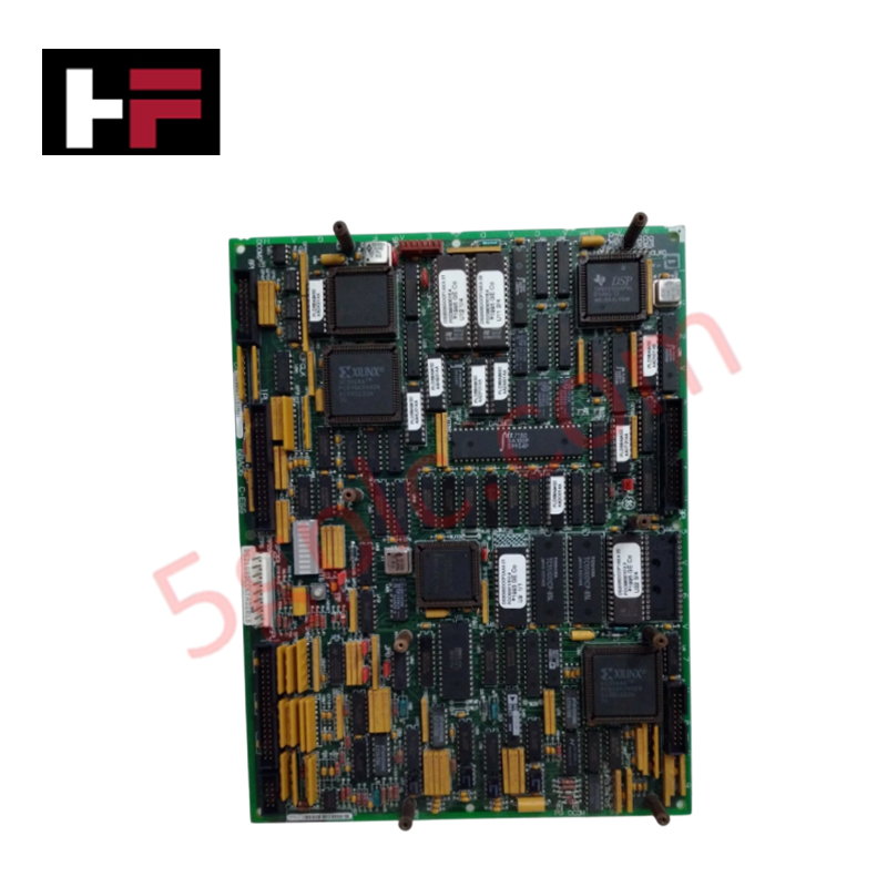
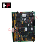
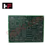
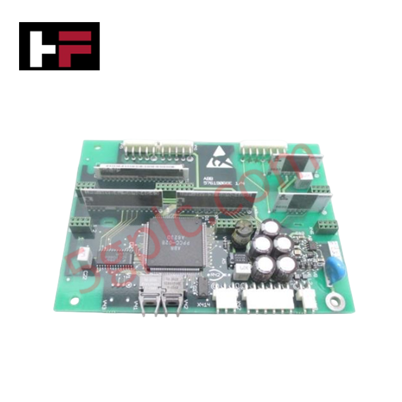
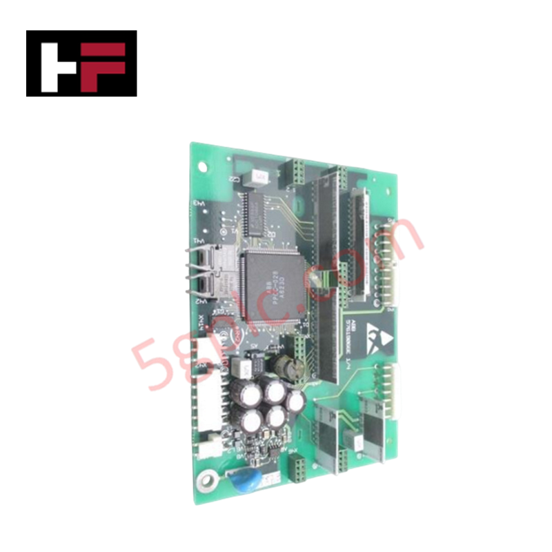
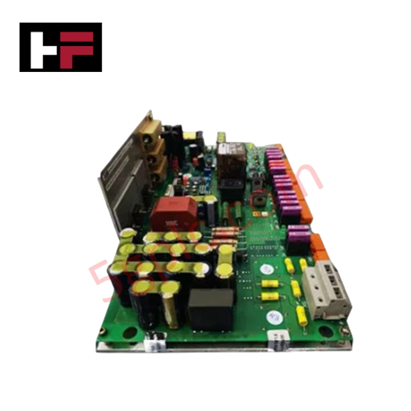
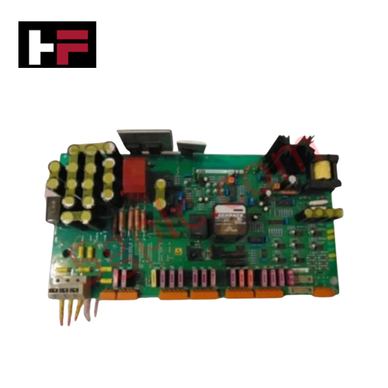
The DS200SDCCG1AGD serves as the primary controller for General Electric's Mark V drive systems. This high-performance Drive Control Board executes the core computational logic required to regulate industrial motor drives and turbine operations. By utilizing a multi-processor architecture, it ensures real-time data processing and synchronized system management. We offer this component as a 100% Brand New, original GE product to guarantee maximum reliability for your critical infrastructure.
Technical Specifications
The DS200SDCCG1AGD integrates advanced processing power with robust diagnostic hardware:
| Component | Technical Detail |
| Manufacturer | GE General Electric |
| Series | Mark V Speedtronic |
| Primary Function | Main Drive Controller |
| Processor Architecture | Three (3) On-board Microprocessors |
| Memory | Multi-access RAM (Simultaneous Multi-processor Access) |
| Diagnostic Interface | Ten (10) LED Fault Indicator Row |
| Configuration Manual | GEI-100029 |
| Programming | Supports Laptop-based Serial Configuration |
Engineering Advantages
-
Parallel Processing Power: Three dedicated microprocessors share access to the on-board RAM simultaneously. This architecture eliminates data bottlenecks and allows the board to execute complex control algorithms with minimal latency.
-
Instantaneous Fault Diagnostics: A row of ten LEDs provides immediate visual feedback. During normal operation, LEDs pulse in pairs from left to right. If a system failure occurs, the board triggers specific LED sequences to display precise fault codes, allowing technicians to identify issues without external tools.
-
Scalable Configuration Deployment: The DS200SDCCG1AGD supports centralized parameter management. Engineers can generate a single configuration file on a laptop and download it to multiple boards across different drives, ensuring system-wide consistency and reducing commissioning time.
-
High-Voltage Resilience: Designed for the demanding environment of GE Motors and Industrial Systems, the board’s layout isolates low-voltage logic from the high-voltage drive components found within the cabinet.
Installation & Safety Protocol
Due to the critical nature of the Drive Control Board, engineers must follow these operational guidelines:
-
Lethal Voltage Awareness: High voltage exists across the board and cabinet components. Never touch any internal parts while the drive receives power.
-
Visual Inspection: To check board health, open the cabinet door and observe the LED sequence. A smooth left-to-right scan indicates healthy operation, while a static "lit-up" row signals a fault code.
-
Parameter Setup: Upon installing a new board, you must configure the parameters to define how the microprocessors analyze data and regulate the drive. Use the tools provided in the GEI-100029 manual to ensure the board matches your specific motor requirements.
FAQs
-
How does the triple-processor system improve performance?
The three microprocessors access the same RAM bank at the same time. This allows the board to handle I/O processing, motor logic, and diagnostic monitoring in parallel rather than sequentially, significantly increasing response speed.
-
What do the ten LEDs signify during a system error?
When the board detects a malfunction, it utilizes the 10-LED row to display a binary or sequential fault code. Refer to the GEI-100029 manual to translate these visual patterns into specific hardware or software errors.
-
Can I use the same configuration for multiple DS200SDCCG1AGD boards?
Yes. You can create a master configuration file on a laptop and download it to numerous boards. This feature is particularly useful for facilities managing multiple identical drive assemblies.
-
Is this board a refurbished or used unit?
No. This listing is for a 100% Brand New original GE unit. It has never been installed, ensuring that the microprocessors and RAM have zero previous operational wear.
Additional Information
- 100% Genuine Parts: All products are original and authentic, ensuring reliable industrial performance.
- 30-Day Refund Guarantee: Return any in-stock item within 30 days in original, unopened packaging for a full refund (excluding shipping and fees).
- 12-Month Warranty: Covers defects in materials or workmanship; excludes misuse, normal wear, or unauthorized modifications.
- Worldwide Shipping: We ship via USPS, UPS, FedEx, and DHL. Delivery times vary by country and may be subject to customs or import fees.
- Support & Contact: Technical and warranty assistance is available anytime. Contact us here: Contact.
- Purchase Guidance: Check product specifications and compatibility carefully before ordering to ensure proper application.


Tech & Buying Guide

The Shift to Flexible IO Modules in Modern Industrial Automation
Traditional control systems rely on dedicated Input Output (IO) cards for industrial automation. Each conventional module processes a single signal type, such as Digital Input (DI), Digital Output (DO), Analog Input (AI), or Analog Output (AO). A standard 16-channel card accepts only one specific channel type across all ports. This inflexible hardware design often creates severe engineering bottlenecks during project execution. Engineers frequently must install entirely new cards to accommodate a single extra sensor. Consequently, late design changes increase control cabinet space requirements and drive up project costs.

DCS Commissioning Steps in Industrial Automation Projects
Commissioning a Distributed Control System (DCS) represents a crucial milestone when deploying modern process automation infrastructure. Field engineers must execute systematic verification steps to transition complex control hardware from static installation to dynamic plant control. Proper commissioning ensures that controllers, I/O modules, network switches, and HMI software operate in strict compliance with engineering design specifications before introducing live process fluids.

PLC and DCS Control System Spares Strategy: Engineering Guidelines
Modern factory automation relies on high-speed fiber optic backbones to link distributed control systems across noise-intensive industrial environments. Unlike copper wiring, optical fibers transmit data via light pulses, making them completely immune to electromagnetic interference (EMI). Field engineers must master optical cable joining and fusion splicing techniques to guarantee low-loss data transmission across critical Programmable Logic Controller (PLC) and Distributed Control System (DCS) nodes.