










Product Details
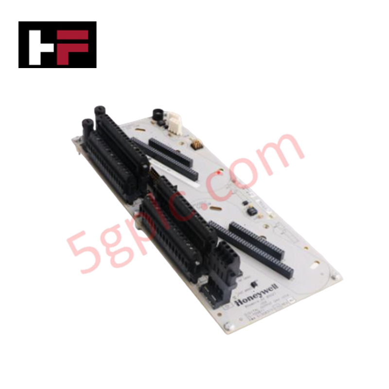
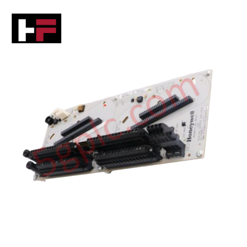
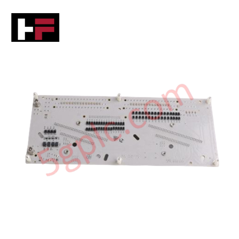
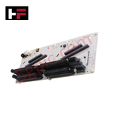
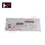
The Honeywell CC-TDOB11, also cataloged as the CC-TDOB11 Digital Output IOTA Redundant, operates as a dedicated hardware component for 24 VDC discrete signal distribution within Experion Series C control network environments. The module provides physical housing and electrical terminal connections for executing two-wire field device switching across a high-density channel matrix.
Hardware Specifications
| Parameter | Specification |
|---|---|
| Model | CC-TDOB11 |
| Brand | Honeywell |
| Series / Module Type | Experion Series C / Digital Output IOTA Redundant |
| Origin | USA |
| Weight | 5 kg (Gross shipping weight) |
| Dimensions | 9 inch length base board profile |
| Operating Temp | -40 to +70 deg C (Standard industrial enclosure range) |
| Power Consumption | 24 VDC nominal system power |
| Channel Density | 32 channels |
| Output Rating | 24 VDC discrete output signals |
| Redundancy Profile | Supported via dual module positioning slots |
Channel-to-Channel Isolation Protocols and Loop Interfacing
The CC-TDOB11 printed circuit layout integrates localized channel-to-channel isolation barriers to limit electromagnetic interference across the 32 discrete output terminals. This internal shielding works in tandem with the primary 24 VDC distribution lines to prevent common-mode noise propagation from distorting nearby low-voltage instrument loops, such as 4-20 mA HART loop protocol runs. The design preserves signal definition at the field terminations by grounding high-frequency cross-talk before it enters the core controller architecture.
Frequently Asked Questions
Q: Does the CC-TDOB11 baseplate support the hot-swap insertion of redundant digital output modules without interrupting active channel loops?
A: Yes. The redundant configuration path allows one digital output card to maintain active processing loops and load current while the adjacent card slot is serviced or replaced under live power conditions.
Q: How is the 24 VDC power routing separated to ensure internal channel-to-channel isolation values are not compromised?
A: The board topology partitions the 32 channels into distinct galvanic zones across a multi-layer copper plane, routing field-side loops independently from the system backplane logic power line.
Field Installation Guidelines
- DIN-Rail Carrier Placement: Mount the 9 inch assembly onto a standard grounding rail inside the terminal cabinet. Verify the integrated chassis grounding clamps are locked onto the bare metal of the rail framework.
- Field Cable Terminations: Wire the 32 field loads to the screw-clamp terminal blocks. Maintain physical segregation between these 24 VDC discrete output wires and high-voltage AC electrical lines to avoid signal degradation.
- Module Insertion Verification: Slide the matching Series C digital output electronic modules into the guidance slots until the retaining mechanisms lock. Misalignment can damage the interface edge connectors and void channel isolation boundaries.
- Thermal Dissipation Space: Allow at least 50 mm of unobstructed clear boundary around the assembly perimeter to sustain adequate convective airflow, preventing internal heat build-up under maximum channel load conditions.
Additional Information
- 100% Genuine Parts: All products are original and authentic, ensuring reliable industrial performance.
- 30-Day Refund Guarantee: Return any in-stock item within 30 days in original, unopened packaging for a full refund (excluding shipping and fees).
- 12-Month Warranty: Covers defects in materials or workmanship; excludes misuse, normal wear, or unauthorized modifications.
- Worldwide Shipping: We ship via USPS, UPS, FedEx, and DHL. Delivery times vary by country and may be subject to customs or import fees.
- Support & Contact: Technical and warranty assistance is available anytime. Contact us here: Contact.
- Purchase Guidance: Check product specifications and compatibility carefully before ordering to ensure proper application.




Tech & Buying Guide

Demystifying CPU Communication Ports in Siemens PLC Architectures
Industrial automation relies heavily on robust data exchange between devices. Without seamless connectivity, field instruments, network switches, human-machine interfaces, and programmable logic controllers cannot coordinate effectively. Therefore, understanding the various CPU communication ports available in Siemens hardware ensures efficient factory automation design and seamless system integration.

Mastering the Siemens PLC Scan Cycle: How the CPU Executes Automation Programs
Industrial automation relies heavily on programmable logic controllers (PLCs) to manage complex manufacturing processes. Many engineers dive straight into programming without mastering the underlying architecture. However, understanding how a PLC CPU executes a program ensures reliable system design. Therefore, mastering the scan cycle optimizes both performance and troubleshooting in modern control systems.

How to Connect to Siemens S7 PLCs: 5 Essential Communication Methods
Establishing a reliable hardware link between a programming terminal and a Siemens SIMATIC controller is essential for engineering workflows. Field engineers rely on distinct physical layers, ranging from legacy serial connections to high-speed Industrial Ethernet protocols. Modern factory automation environments prioritize fast data transfer and seamless driver integration. Selecting the correct connection method simplifies program downloads, online monitoring, and system troubleshooting in complex control systems.