

Product Details
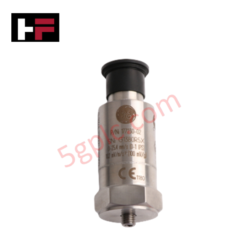
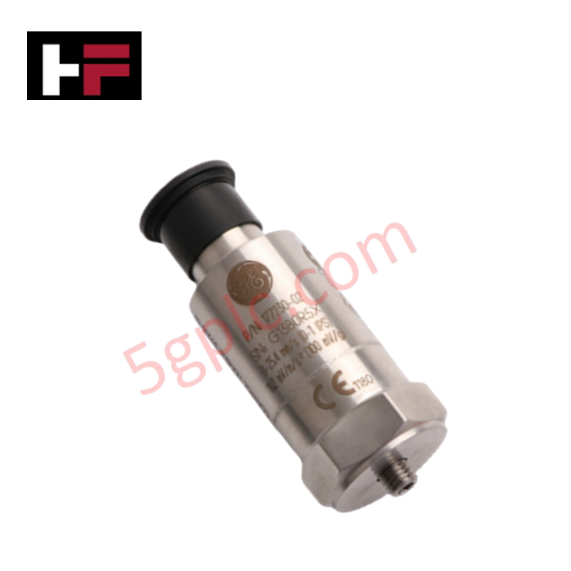
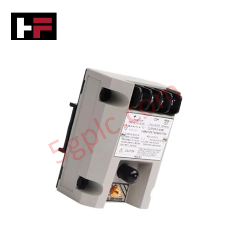
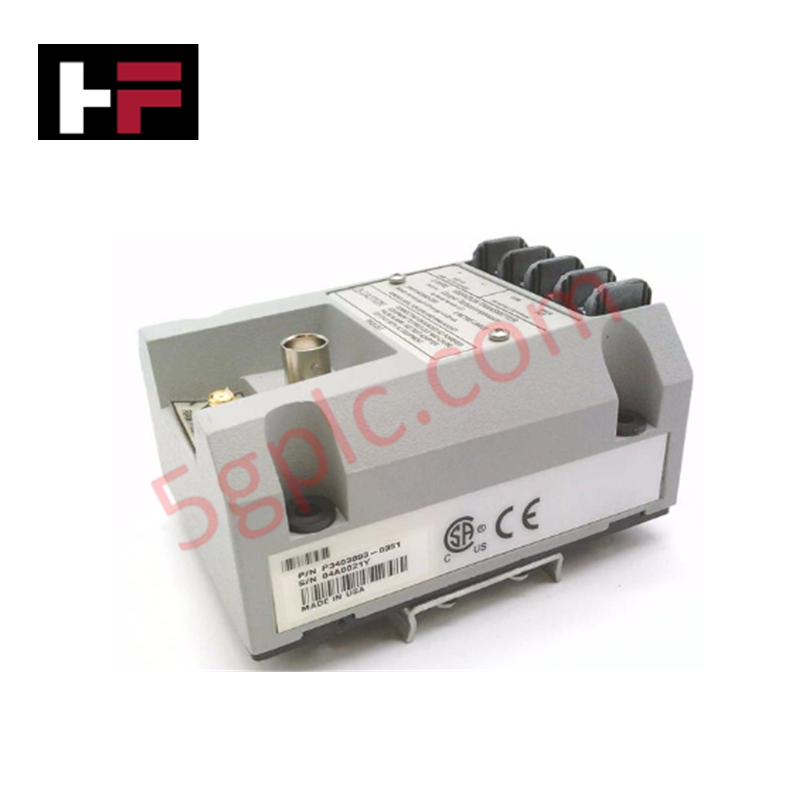
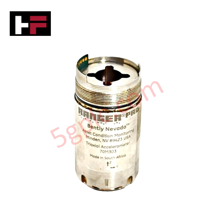
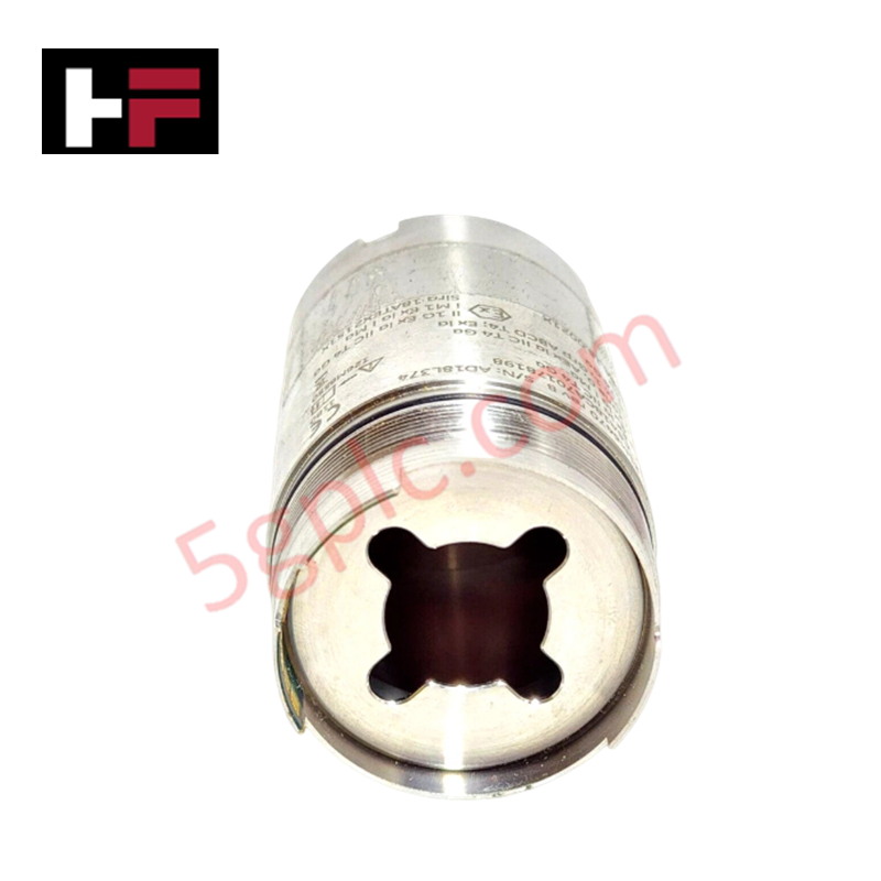
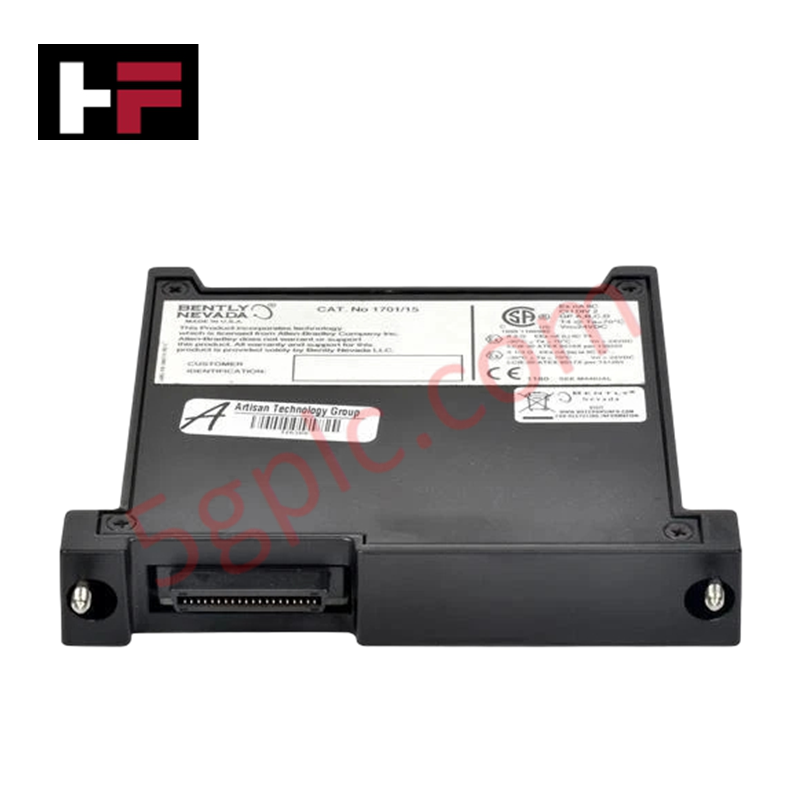
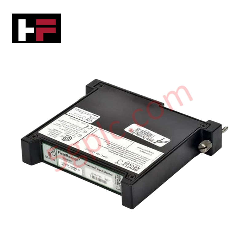
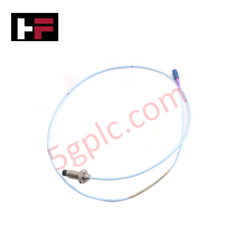
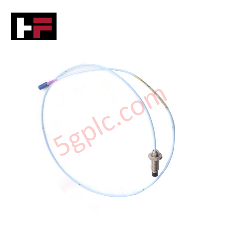
Configured for dynamic vibration monitoring and overall velocity signal acquisition in machinery protection platforms, the Bently Nevada 177230-02 (177230 Seismic Transmitter) provides direct physical/electrical execution.
Hardware Specifications
| Parameter | Specification |
|---|---|
| Model | 177230-02 |
| Brand | Bently Nevada |
| Origin | USA |
| Weight | 0.131 kg (Shipping weight: 1.5 kg) |
| Dimensions | Height: 66.0 mm (2.60 in), Diameter: 25.4 mm (1.00 in) |
| Operating Temp | -40 deg C to +85 deg C (-40 deg F to +185 deg F) |
| Power Consumption | Loop-powered via 4-20 mA current loop |
| Measurement Range | 0 to 50.8 mm/s (0 to 2.0 in/s) |
| Connector Type | 3-pin MIL-C-5015 |
| Case Material | 316L Stainless Steel |
| Electrical Isolation | Greater than 10^9 ohms |
Rotor Dynamics and Seismic Signal Processing
The 177230-02 seismic transmitter integrates solid-state piezoceramic sensing elements and conditioning electronics to evaluate rotor dynamics and structural casing vibration. Internal signal processing converts raw acceleration forces into a peak-velocity 4-20 mA current loop signal proportional to the specified 0 to 50.8 mm/s (0 to 2.0 in/s) vibration amplitude. Electrical isolation exceeding 10^9 ohms prevents ground loops and suppresses parasitic signal cross-talk between adjacent sensor channels on rotating machinery housings.
Frequently Asked Questions
Q: How is signal loop integrity maintained over long cable runs?
A: The transmitter utilizes a 4-20 mA loop-powered topology over its 3-pin MIL-C-5015 connector interface, minimizing voltage drop attenuation and EMI noise susceptibility over extended field wiring lengths.
Q: What is the isolation capability between the internal circuit and the transmitter housing?
A: The internal transducer circuitry provides galvanic and physical isolation exceeding 10^9 ohms relative to the 316L stainless steel outer casing.
Field Installation Guidelines
- Mount the transmitter vertically onto a smooth, flat, machined metal surface on the bearing housing using a dedicated threaded stud.
- Ensure the mounting surface is free of paint, corrosion, and surface irregularities to maintain solid physical contact for accurate high-frequency transmission.
- Torque the transducer mounting stud to standard engineering limits (typically 3.4 N-m to 6.8 N-m) to prevent housing distortion or resonance decoupling.
- Align and mate the 3-pin MIL-C-5015 cable connector assembly onto the transmitter top header, fully tightening the threaded coupling nut.
- Cable shielding must be connected to ground at one end only—typically at the control system rack ground—to prevent ground loop noise from corrupting loop telemetry.
Additional Information
- 100% Genuine Parts: All products are original and authentic, ensuring reliable industrial performance.
- 30-Day Refund Guarantee: Return any in-stock item within 30 days in original, unopened packaging for a full refund (excluding shipping and fees).
- 12-Month Warranty: Covers defects in materials or workmanship; excludes misuse, normal wear, or unauthorized modifications.
- Worldwide Shipping: We ship via USPS, UPS, FedEx, and DHL. Delivery times vary by country and may be subject to customs or import fees.
- Support & Contact: Technical and warranty assistance is available anytime. Contact us here: Contact.
- Purchase Guidance: Check product specifications and compatibility carefully before ordering to ensure proper application.


Tech & Buying Guide

Voice-Activated Industrial Automation: Integrating Speech Control into PLC and DCS Architectures
Industrial automation integrates speech recognition, IIoT protocols, and NLP with PLCs and DCS to streamline operations. By leveraging advanced edge computing, engineers enable real-time, hands-free control—allowing personnel to manage smart factory processes safely away from hazardous equipment.
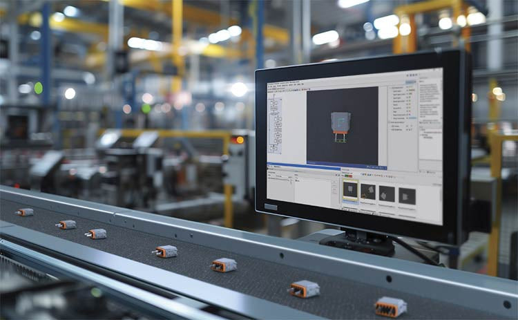
Modern Industrial Automation: Transforming Safety and Efficiency in Mining Operations
Industrial automation has evolved from a simple manufacturing tool into the operational backbone of high-risk sectors. Modern mining operations increasingly rely on advanced control systems, programmable logic controllers (PLCs), distributed control systems (DCS), and artificial intelligence to address deep-underground hazards. By replacing manual labor in high-risk zones, factory automation technologies protect personnel while significantly boosting operational throughput.