


Product Details
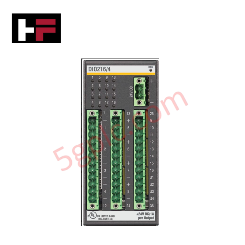
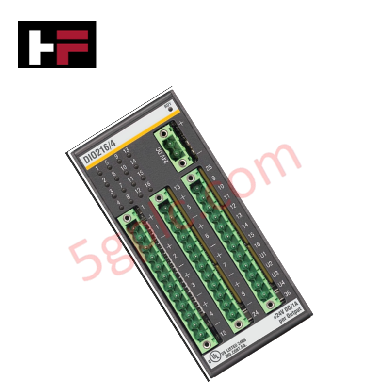
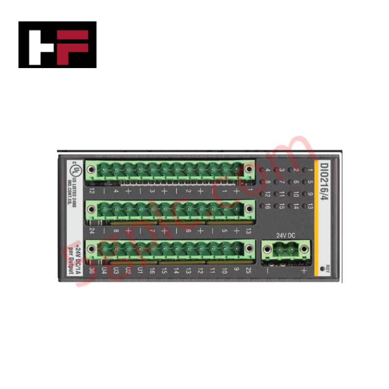
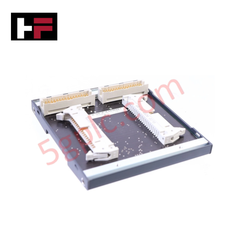
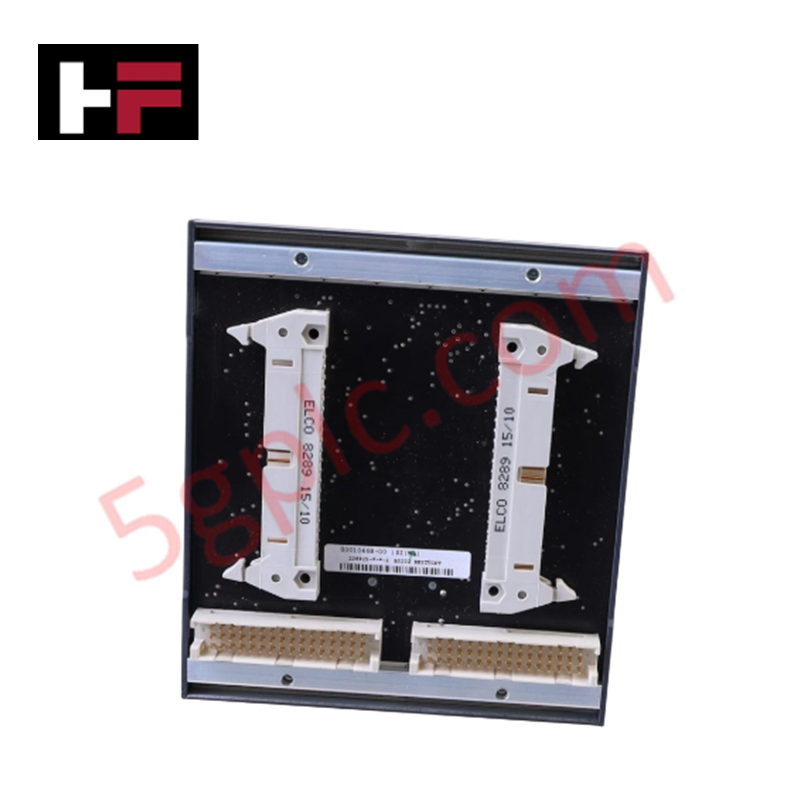
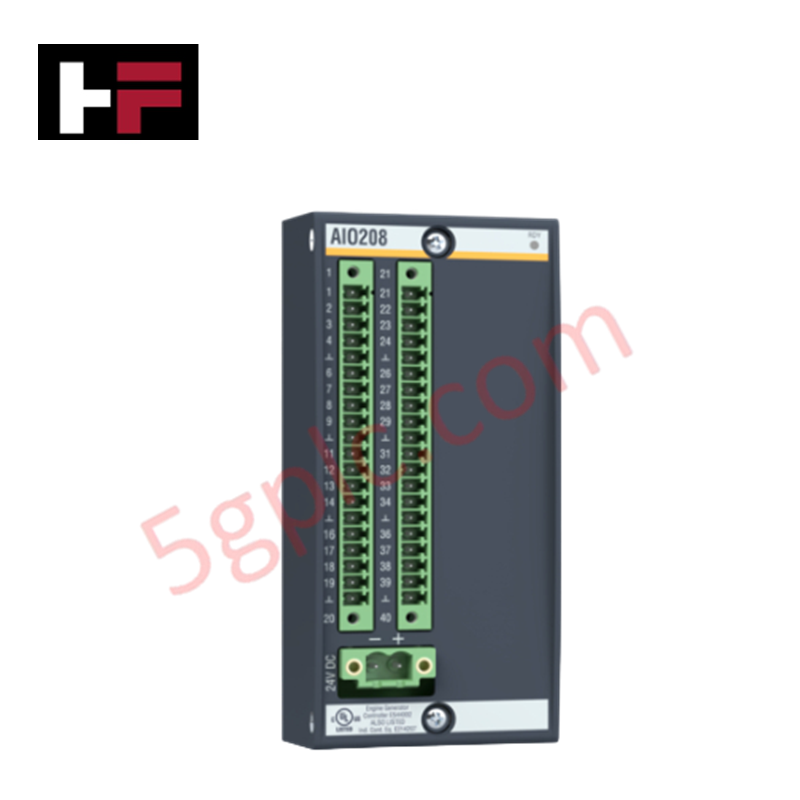
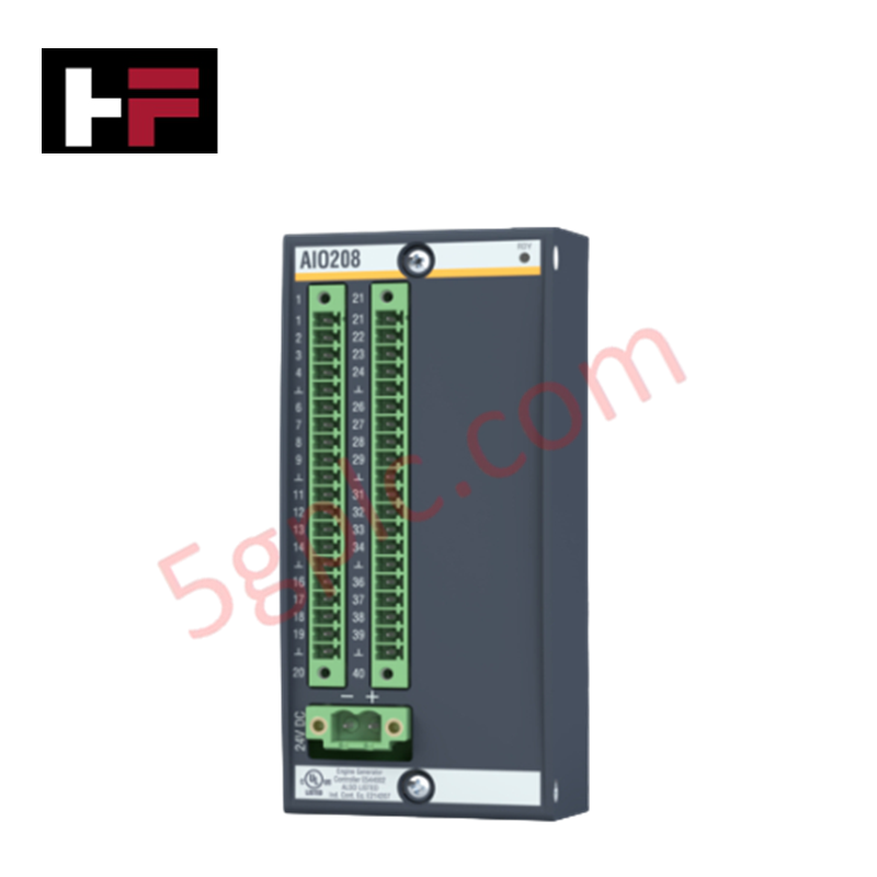
Configured for discrete signal processing in modular control platforms, the Bachmann DIO216/4 (DIO216/4 Digital I/O Module) provides direct electrical execution for 16 configurable digital channels.
Hardware Specifications
| Parameter | Specification |
|---|---|
| Model | DIO216/4 |
| Brand | Bachmann |
| Origin | Austria |
| Dimensions | Standard Bachmann module enclosure |
| I/O Channels | 16 (4 groups of 4) |
| Input Voltage (High) | 15 VDC to 34 VDC |
| Input Voltage (Low) | 0 VDC to 5 VDC |
| Max Output Current | 1 A per channel / 16 A total |
| Input Delay | 600 us |
Profinet / EtherNet/IP Deterministic Networks
The DIO216/4 integrates into Bachmann controller systems to facilitate high-speed, deterministic data exchange. The module supports cycle-time-consistent communication, ensuring that digital state transitions are synchronized with the PLC scan cycle. To optimize deterministic performance in networked environments, users must configure the appropriate firmware flash compatibility settings to ensure the module recognizes the backplane bus communication velocity correctly. Channel grouping into four distinct sets allows for localized common-point wiring, while the inclusion of an interrupt-capable channel enables time-critical event triggering without relying on standard polling latencies.
Frequently Asked Questions
Q: Is the DIO216/4 capable of hot-swapping during system operation?
A: Module replacement procedures must adhere to the specific Bachmann system documentation regarding power-on status and backplane communication integrity. Verify if the specific backplane configuration supports hot-insertion without inducing bus errors.
Q: How should the internal resistance be accounted for in signal wiring?
A: The internal resistance of 6.8 kOhm influences the current draw on the input signal source. Ensure that the external field device output impedance is sufficient to drive the logic levels within the specified 15 VDC to 34 VDC range.
Field Installation Guidelines
- Ensure the module is properly seated in the designated rack slot to establish a secure connection with the backplane bus.
- Utilize shielded cabling for signal runs exceeding 3 metres to prevent electromagnetic interference from affecting the 600 us response time.
- Verify that the common ground for input and output groups is consistent with the system power supply to prevent ground potential differences.
- When wiring inductive loads to the outputs, ensure external flyback diodes are installed to suppress voltage spikes and protect the output transistors.
- Monitor the channel-specific green LED status indicators during initial commissioning to confirm proper signal state detection and output activation.
Additional Information
- 100% Genuine Parts: All products are original and authentic, ensuring reliable industrial performance.
- 30-Day Refund Guarantee: Return any in-stock item within 30 days in original, unopened packaging for a full refund (excluding shipping and fees).
- 12-Month Warranty: Covers defects in materials or workmanship; excludes misuse, normal wear, or unauthorized modifications.
- Worldwide Shipping: We ship via USPS, UPS, FedEx, and DHL. Delivery times vary by country and may be subject to customs or import fees.
- Support & Contact: Technical and warranty assistance is available anytime. Contact us here: Contact.
- Purchase Guidance: Check product specifications and compatibility carefully before ordering to ensure proper application.


Tech & Buying Guide

Strategic Selection: Choosing the Right SCADA Software for Your PLC Project
In industrial automation, the SCADA (Supervisory Control and Data Acquisition) system acts as the bridge between raw machine data and actionable human intelligence. Selecting the incorrect software platform can lead to integration bottlenecks, scalability issues, and excessive long-term maintenance costs. As an automation consultant with 15 years of experience, I have guided many projects through the selection process. Below are the essential criteria for choosing a platform that ensures both performance and longevity.

Ensuring Operational Continuity: The Strategic Value of Redundant Automation Systems
In modern industrial landscapes, unplanned downtime is the ultimate adversary. For sectors relying on complex PLC and DCS architectures, a single hardware failure can trigger catastrophic production losses. Therefore, implementing redundant automation systems is no longer a luxury; it is a fundamental requirement for mission-critical operations. In this article, I analyze why redundancy remains the backbone of reliable industrial infrastructure.

Selecting the Right Cables for Industrial Automation: A Comprehensive Guide
Selecting the appropriate cabling infrastructure is critical for the success of any industrial automation project. Improper cable selection often leads to signal degradation, system instability, and costly downtime. As an automation engineer, I frequently see projects compromised by poor cabling choices in harsh industrial environments. This guide simplifies the complex landscape of cabling to help you make informed decisions for your PLC, DCS, and control systems.