










Product Details
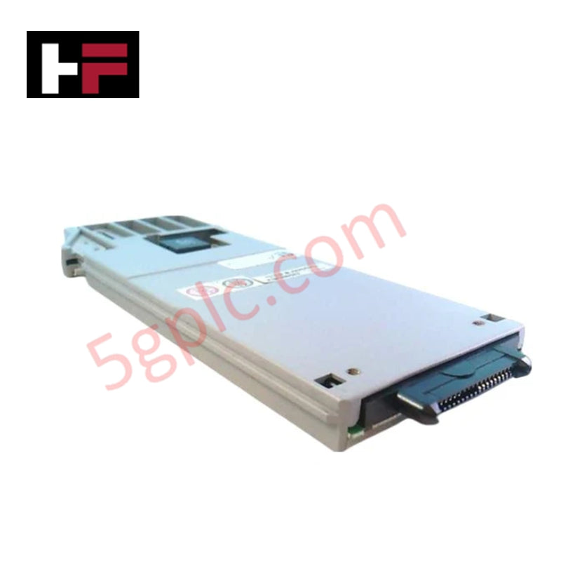
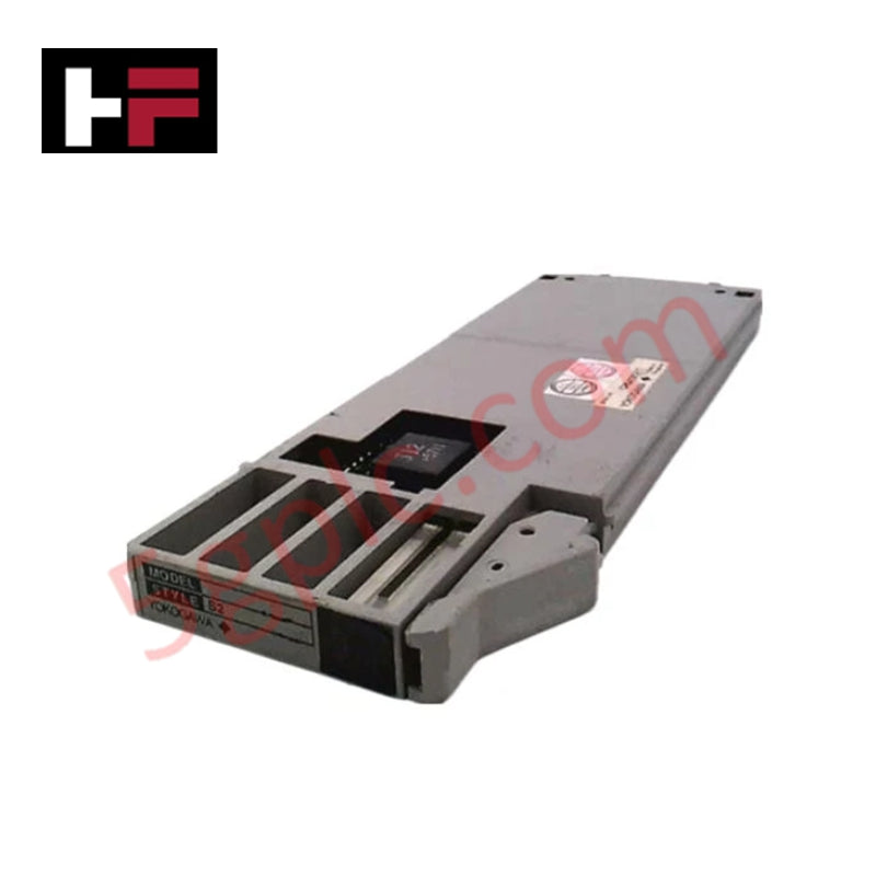
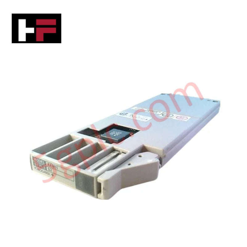
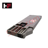
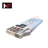
The YOKOGAWA AAM11-S2, also cataloged as the AAM11 Signal Conditioning Module, operates as a dedicated hardware component for pulse signal conversion and auxiliary output execution within YOKOGAWA CENTUM control system networks. The module converts contact, voltage, and current pulse signals for nest-mounted adapter interfaces.
Suffix Breakdown & Model Matrix
The catalog designation defines the hardware version and installation profile:
- Base Model (AAM11): Signal conditioning module architecture for pulse signal conversion
- Suffix (-S2): Hardware revision level and interface parameter set for I/O adapter nest mounting
Hardware Specifications
| Parameter | Specification |
|---|---|
| Model | AAM11-S2 |
| Brand | YOKOGAWA |
| Origin | Japan |
| Power Consumption | 46 mA max (24.0 VDC system), 10 mA max (5.0 VDC internal logic) |
| Input Signal Types | Contact, voltage, and current pulse signals |
| Power Supply Rails | 24.0 VDC system power, 5.0 VDC internal logic power |
| Dielectric Strength | 1500 VAC for 1 minute |
| Physical Interface | ELCO connector or M4 screw terminals via A2BA3D nest |
Channel-to-Channel Isolation and 4-20 mA HART Loop Signal Integrity
The AAM11-S2 processes incoming pulse signals while maintaining electrical isolation between field loops and system logic. The module provides isolated transistor contact pulse generation to deliver signal conditioning across auxiliary control paths. High dielectric isolation rated at 1500 VAC for 1 minute prevents common-mode voltage propagation, maintaining signal fidelity across 4-20 mA HART loop protocol architectures and DCS networks.
Frequently Asked Questions
Q: What power supply parameters are required for the operation of the AAM11-S2 module?
A: The module requires a 24.0 VDC system power supply drawing 46 mA or lower, along with a 5.0 VDC internal logic power supply drawing 10 mA or lower.
Q: How is the AAM11-S2 physically mounted and wired in a control cabinet?
A: The module mounts directly onto an I/O adapter nest (A2BA3D), utilizing M4 screws or ELCO multi-pin connectors for field wiring terminations.
Field Installation Guidelines
Disconnect system power before installing or servicing the AAM11-S2 module within the I/O adapter nest. Seat the module firmly onto the A2BA3D nest socket and tighten M4 retaining hardware or engage ELCO connector latches completely to ensure mechanical stability. Route field wiring away from high-voltage AC lines and terminate all cable shields at a single earth grounding bar inside the cabinet enclosure.
Additional Information
- 100% Genuine Parts: All products are original and authentic, ensuring reliable industrial performance.
- 30-Day Refund Guarantee: Return any in-stock item within 30 days in original, unopened packaging for a full refund (excluding shipping and fees).
- 12-Month Warranty: Covers defects in materials or workmanship; excludes misuse, normal wear, or unauthorized modifications.
- Worldwide Shipping: We ship via USPS, UPS, FedEx, and DHL. Delivery times vary by country and may be subject to customs or import fees.
- Support & Contact: Technical and warranty assistance is available anytime. Contact us here: Contact.
- Purchase Guidance: Check product specifications and compatibility carefully before ordering to ensure proper application.


Tech & Buying Guide

Understanding Siemens PLC Memory Cards: MMC, SMC, and SD Solutions in Industrial Automation
Memory management plays a pivotal role in maintaining control system reliability across modern manufacturing plants. Industrial control systems rely on specialized memory cards to store project logic, firmware updates, and retentive system data. Siemens uses several memory architectures, including Micro Memory Cards (MMC) and SIMATIC Memory Cards (SMC). Engineers must understand these hardware variations to ensure zero data loss and minimize downtime during maintenance routines.

Redefining Control Systems: The Rise of Flexible I/O Modules in Industrial Automation
Conventional input-output architectures often limit engineering agility and inflate long-term inventory costs. Today, Flexible Input/Output Modules (FIOM) are transforming how control system engineers design, commission, and maintain automation infrastructure. By allowing individual channel software configuration, FIOM technology bridges the gap between rigid hardware design and dynamic plant requirements.

Understanding Modern SCADA Systems: Architecture, Communication Topologies, and Industrial Applications
Supervisory Control and Data Acquisition (SCADA) systems form the digital backbone of modern industrial automation. They collect critical field data, transmit signals across vast distances, and empower plant operators with real-time process visibility. Across modern infrastructures, SCADA solutions streamline centralized control and maintain continuous operational uptime.