


Product Details
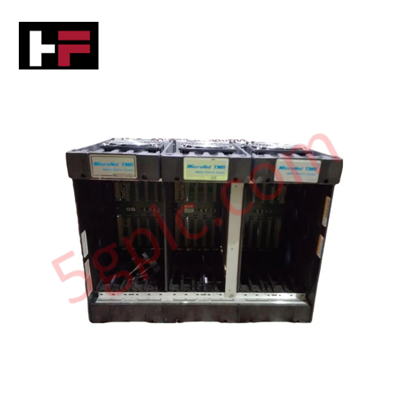
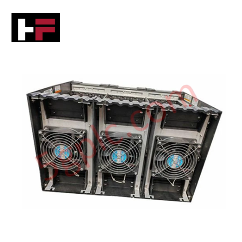
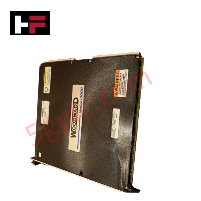
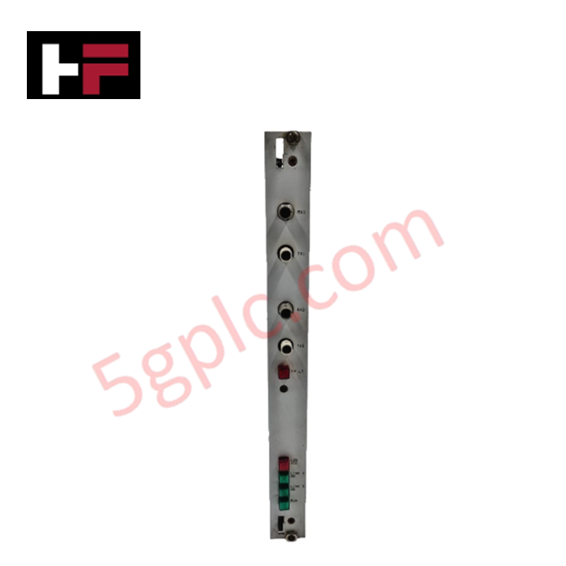
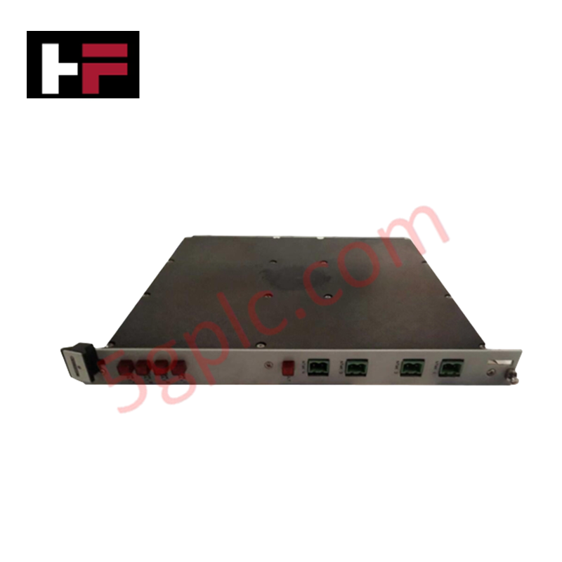
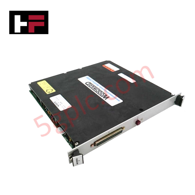
Configured for high-availability control processing in MicroNet architectures, the Woodward 5453-279 (5453-279 TMR Chassis) provides direct physical execution of module integration for central processing units, kernel power supplies, and up to twelve I/O modules.
Hardware Specifications
| Parameter | Specification |
|---|---|
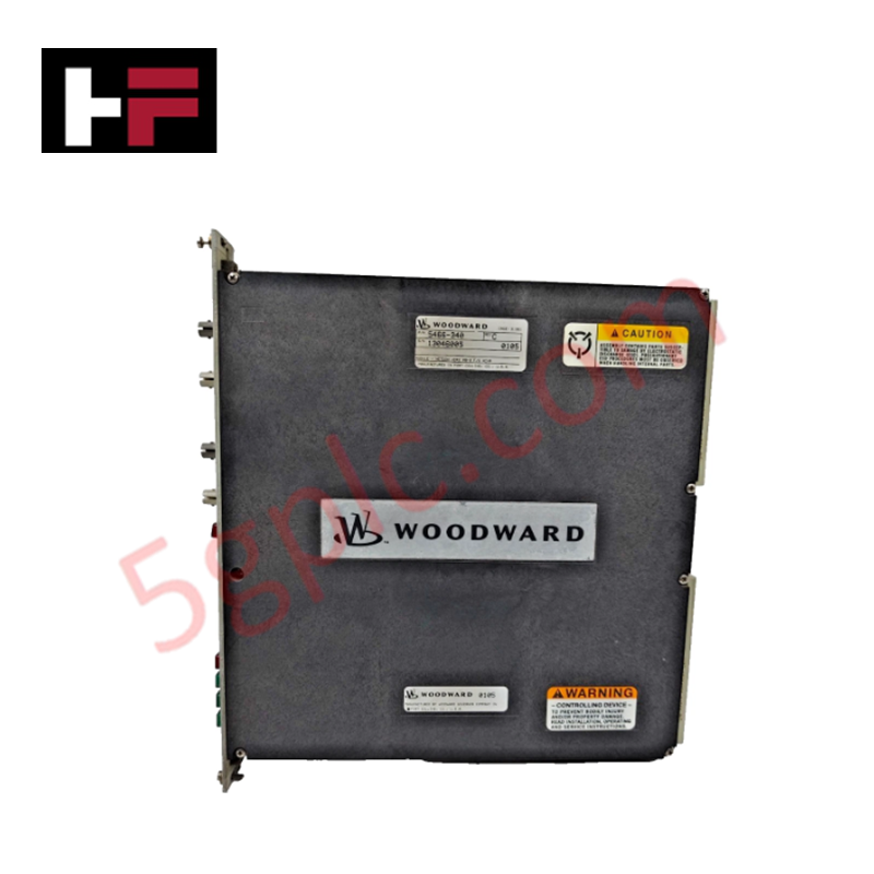
| Model | 5453-279 |
| Brand | Woodward |
| Origin | USA |
| I/O Capacity | Up to 12 modules |
| Architecture | Triple Modular Redundant (TMR) |
Actuator Loop Feedback Response and Thermal Heat Sink Dissipation Profiles
The 5453-279 chassis serves as the physical backbone for the MicroNet TMR system, housing critical processing and signal conditioning components. The chassis architecture supports distinct communication topologies based on the processor type: TMR5200 CPUs utilize RTN networks for shared I/O operations, while TMR040 configurations employ transceiver-based dedicated cabling. Consistent thermal heat sink dissipation profiles must be maintained within the cabinet to ensure the long-term integrity of the backplane bus and module connectors. By providing a rigid mechanical interface for redundant components, the chassis preserves signal timing and actuator loop feedback response, ensuring that the voting logic remains synchronous across all processor channels.
Frequently Asked Questions
Q: Does the chassis support mixed-processor configurations?
A: The backplane design is optimized for specific processor architectures. Mixing TMR5200 and TMR040 communication methods within the same chassis backplane is not supported; the configuration must align with the chosen CPU series and transceiver implementation.
Q: Are there specific limitations when populating the full 12-slot I/O capacity?
A: Populating all twelve slots requires careful consideration of the power distribution backplane capacity. Ensure that the total power consumption of the installed modules, including I/O and CPU loads, does not exceed the thermal or electrical limits defined by the installed power supply configuration.
Field Installation Guidelines
- Mounting: Secure the chassis to a rigid, grounded cabinet backplane. Ensure adequate clearance for module extraction and cable routing for the CPU transceiver connections.
- Grounding: Establish a low-impedance connection between the chassis frame and the cabinet protective earth (PE) bus to mitigate electromagnetic interference on the backplane communication signals.
- Module Seating: When installing I/O or CPU modules, verify that the insertion force is uniform and that the module is locked into the backplane guide rails to ensure positive connector engagement.
- Cable Management: For TMR040 configurations, use high-quality shielded cabling for transceivers. Route these cables separate from high-voltage power lines to prevent signal crosstalk and potential data corruption.
Additional Information
- 100% Genuine Parts: All products are original and authentic, ensuring reliable industrial performance.
- 30-Day Refund Guarantee: Return any in-stock item within 30 days in original, unopened packaging for a full refund (excluding shipping and fees).
- 12-Month Warranty: Covers defects in materials or workmanship; excludes misuse, normal wear, or unauthorized modifications.
- Worldwide Shipping: We ship via USPS, UPS, FedEx, and DHL. Delivery times vary by country and may be subject to customs or import fees.
- Support & Contact: Technical and warranty assistance is available anytime. Contact us here: Contact.
- Purchase Guidance: Check product specifications and compatibility carefully before ordering to ensure proper application.


Tech & Buying Guide

Understanding Dry Contacts in PLC Wiring: An Industrial Automation Guide
Mastering contact switching principles is essential for reliable control panels. Field devices and PLCs interface through dry or wet contacts. This technical guide examines the mechanics of dry contacts, explores their wiring architectures, and evaluates their key advantages in industrial automation.

Ultimate Commissioning Checklist for Industrial Automation Systems: An Engineering Guide
Commissioning is the most decisive phase of an industrial automation project, transforming control hardware and software into an operational facility. Thorough testing prevents costly startup delays and builds customer confidence. This guide covers essential checklists, electrical standards, and best practices.

Redundant Automation Systems: Core Architecture, Business Value, and Technical Advantages
Unplanned downtime poses a major financial threat to process manufacturing. To prevent costly interruptions, engineers deploy redundant PLC and DCS architectures that ensure continuous operation when hardware fails. This technical guide explores redundancy principles, critical system nodes, and real-world scenarios.